Category Archives: Technology

Aliasing when shooting 2K with a 4K sensor (FS700, PMW-F5, PMW-F55 and others).

There is a lot of confusion and misunderstanding about aliasing and moiré. So I’ve thrown together this article to try and explain whats going on and what you can (or can’t) do about it.

Sony’s FS700, F5 and F55 cameras all have 4K sensors. They also have the ability to shoot 4K raw as well as 2K raw when using Sony’s R5 raw recorder. The FS700 will also be able to shoot 2K raw to the Convergent Design Odyssey. At 4K these cameras have near zero aliasing, at 2K there is the risk of seeing noticeable amounts of aliasing.

One key concept to understand from the outset is that when you are working with raw the signal out of the camera comes more or less directly from the sensor. When shooting non raw then the output is derived from the full sensor plus a lot of extra very complex signal processing.

First of all lets look at what aliasing is and what causes it.

Aliasing shows up in images in different ways. One common effect is a rainbow of colours across a fine repeating pattern, this is called moiré. Another artefact could be lines and edges that are just a little off horizontal or vertical appearing to have stepped or jagged edges, sometimes referred to as “jaggies”.

But what causes this and why is there an issue at 2K but not at 4K with these cameras?

Lets imagine we are going to shoot a test pattern that looks like this:

Test pattern, checked shirt or other similar repeating pattern.

And lets assume we are using a bayer sensor such as the one in the FS700, F5 or F55 that has a pixel arrangement like this, although it’s worth noting that aliasing can occur with any type of sensor pattern or even a 3 chip design:

Sensor with bayer pattern.

Now lets see what happens if we shoot our test pattern so that the stripes of the pattern line up with the pixels on the sensor. The top of the graphic below represents the pattern or image being filmed, the middle is the sensor pixels and the bottom is the output from the green pixels of the sensor:

Test pattern aligned with the sensor pixels.

As we can see each green pixel “see’s” either a white line or a black line and so the output is a series of black and white lines. Everything looks just fine… or is it? What happens if we move the test pattern or move the camera just a little bit. What if the camera is just a tiny bit wobbly on the tripod? What if this isn’t a test pattern but a striped or checked shirt and the person we are shooting is moving around? In the image below the pattern we are filming has been shifted to the left by a small amount.

Test pattern miss-aligned with pixels.

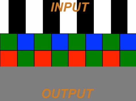
Now look at the output, it’s nothing but grey, the black and white pattern has gone. Why? Simply because the green pixels are now seeing half of a white bar and half of a black bar. Half white plus half black equals grey, so every pixel see’s grey. If we were to slowly pan the camera across this pattern then the output would alternate between black and white lines when the bars and pixels line up and grey when they don’t. This is aliasing at work. Imagine the shot is of a person with a checked shirt, as the person moves about the shirt will alternate between being patterned and being grey. As the shirt will be not be perfectly flat and even, different parts of the shirt will go in and out of sync with the pixels so some parts will be grey, some patterned, it will look blotchy. A similar thing will be happening with any colours, as the red and blue pixels will sometimes see the pattern at other times not, so the colours will flicker and produce strange patterns, this is the moiré that can look like a rainbow of colours.

So what can be done to stop this?

Well what’s done in the majority of professional level cameras is to add a special filter in front of the sensor called an optical low pass filter (OPLF). This filter works by significantly reducing the contrast of the image falling on the sensor at resolutions approaching the pixel resolution so that the scenario above cannot occur. Basically the image falling on the sensor is blurred a little so that the pixels can never see only black or only white. This way we won’t get flickering between black & white and then grey if there is any movement. The downside to this is that it does mean that some contrast and resolution will be lost, but this is better than having flickery jaggies and rainbow moiré. In effect the OLPF is a type of de-focusing filter (for the techies out there it is usually something called a birefringent filtre). The design of the OLPF is a trade off between how much aliasing is acceptable and how much resolution loss is acceptable. The OLPF cut-off isn’t instant, it’s a sharp but gradual cut-off that starts somewhere lower than the sensor resolution, so there is some undesirable but unavoidable contrast loss on fine details. The OLPF will be optimised for a specific pixel size and thus image resolution, but it’s a compromise. In a 4K camera the OLPF will start reducing the resolution/contrast before it gets to 4K.

(As an aside, this is one of the reasons why shooting with a 4K camera can result in better HD, because the OLPF in an HD camera cuts contrast as we approach HD, so the HD is never as sharp and contrasty as perhaps it could be. But shoot at 4K and down-convert and you can get sharper, higher contrast HD).

So that’s how we prevent aliasing, but what’s that got to do with 2K on the FS700, F5 and F55?

Well the problem is this, when shooting 2K raw or in the high speed raw modes Sony are reading out the sensor in a way that creates a larger “virtual” pixel. This almost certainly has to be done for the high speed modes to reduce the amount of data that needs to be transferred from the sensor and into the cameras processing and recording circuits when using high frame rates.  I don’t know exactly how Sony are doing this but it might be something like my sketch below:

Using adjacent pixels to create larger virtual pixels.

So instead of reading individual pixels, Sony are probably reading groups of pixels together to create a 2K bayer image. This creates larger virtual pixels and in effect turns the sensor into a 2k sensor. It is probably done on the sensor during the read out process (possibly simply by addressing 4 pixels at the same time instead of just one) and this makes high speed continuous shooting possible without overheating or overload as there is far less data to read out.

But, now the standard OLPF which is designed around the small 4K isn’t really doing anything because in effect the new “virtual” pixels are now much larger than the original 4K pixels the OLPF was designed around. The standard OLPF cuts off at 4K so it isn’t having any effect at 2K, so a 2K resolution pattern can fall directly on our 2K virtual bayer pixels and you will get aliasing. (There’s a clue in the filter name: optical LOW PASS filter, so it will PASS any signals that are LOWer than the cut off. If the cut off is 4K, then 2K will be passed as this is lower than 4K, but as the sensor is now in effect a 2K sensor we now need a 2K cut off).

On the FS700 there isn’t (at the moment at least) a great deal you can do about this. But on the F5 and F55 cameras Sony have made the OLPF replaceable. By loosening one screw the 4K OLPF can be swapped out with a 2K OLPF in just a few seconds. The 2K OLPF will control aliasing at 2K and high speed and in addition it can be used if you want a softer look at 4K. The contrast/resolution reduction the filter introduces at 2K will give you a softer “creamier” look at 4K which might be nice for cosmetic, fashion, period drama or other similar shoots.

Replacing the OLPF on a Sony PMW-F5 or PMW-F55. Very simple.

Fs700 owners wanting to shoot 2K raw will have to look at adding a little bit of diffusion to their lenses. Perhaps a low contrast filter will help or a net or stocking over the front of the lens to add some diffusion will work to slightly soften the image and prevent aliasing. Maybe someone will bring out an OLPF that can be fitted between the lens and camera body, but for the time being to prevent aliasing on the FS700 you need to soften, defocus or blur the image a little to prevent the camera resolving detail above 2K. Maybe using a soft lens will work or just very slightly de-focussing the image.

But why don’t I get aliasing when I shoot HD?

Well all these cameras use the full 4K sensor when shooting HD. All the pixels are used and read out as individual pixels. This 4K signal is then de-bayered into a conventional 4K video signal (NOT bayer). This 4K (non raw) video will not have any significant aliasing as the OLPF is 4K and the derived video is 4K. Then this conventional video signal is electronically down-converted to HD. During the down conversion process an electronic low pass filter is then used to prevent aliasing and moiré in the newly created HD video. You can’t do this with raw sensor data as raw is BEFORE processing and derived directly from the sensor pixels, but you can do this with conventional video as the HD is derived from a fully processed 4K video signal.

I hope you understand this. It’s not an easy concept to understand and even harder to explain. I’d love your comments, especially anything that can add clarity to my explanation.

UPDATE: It has been pointed out that it should be possible to take the 4K bayer and from that use an image processor to produce a 2K anti-aliased raw signal.

The problem is that, yes in theory you can take a 4K signal from a bayer sensor into an image processor and from that create an anti-aliased 2K bayer signal. But the processing power needed to do this is incredible as we are looking at taking 16 bit linear sensor data and converting that to new 16 bit linear data. That means using DSP that has a massive bit depth with a big enough overhead to handle 16 bit in and 16 bit out. So as a minimum an extremely fast 24 bit DSP or possibly a 32 bit DSP working with 4K data in real time. This would have a big heat and power penalty and I suspect is completely impractical in a compact video camera like the F5/F55. This is rack-mount  high power work station territory at the moment. Anyone that’s edited 4K raw will know how processor intensive it is trying to manipulate 16 bit 4K data.

When shooting HD your taking 4K 16 bit linear sensor data, but your only generating 10 bit HD log or gamma encoded data, so the processing overhead is tiny in comparison and a 16 bit DSP can quite happily handle this, in fact you could use a 14 bit DSP by discarding the two LSB’s as these would have little effect on the final 10 bit HD.

For the high speed modes I doubt there is any way to read out every pixel from sensor continously without something overheating. It’s probably not the sensor that would overheat but the DSP. The FS700 can actually do 120fps at 4K for 4 seconds, so clearly the sensor can be read in it’s entirety at 4K and 120fps, but my guess is that something gets too hot for extended shooting times.

So this means that somehow the data throughput has to be reduced. The easiest way to do this is to read adjacent pixel groups. This can be done during the readout by addressing multiple pixels together (binning). If done as I suggest in my article this adds a small degree of antialising. Sony have stated many times that they do not pixel or line skip and that ever pixel is used at 2K, but either way, whether you line skip or pixel bin the effective pixel pitch increases and so you must also change the OLPF to match.

Shimming Nikon to Canon Lens Adapters. Helps get your zooms to track focus.

I use a lot of different lenses on my large sensor video cameras. Over the years I’ve collected quite a collection of Nikon and Canon mount lenses. I like Nikon mount lenses because they still have an iris that can be controlled manually. I don’t like Nikon lenses because most of them focus back-to-front compared to broadcast, PL and Canon lenses. The exception to this is Sigma lenses. The vast majority of Sigma lenses with Nikon mounts focus the right way – anti clockwise for infinity. If you go back just a few years you’ll find a lot of Sigma, Nikon mount lenses that focus the right way and have a manual iris ring. These are a good choice for use on video cameras. You don’t need any fancy adapters with electronics or extra mechanical devices to use these lenses and you know exactly what your aperture is.

But…. Canon lenses have some advantages too. First is the massive range of lenses out there. Then there is the ability to have working optical image stabilisation if you have an electronic mount and the possibility to remotely control the iris and focus. The down side is you need some kind of electronic mount adapter to make most of them work. But as I do own a couple of Canon DSLR’s it is useful to have a few Canon lenses.

So for my F3, initially I used Nikon lenses. Then along came the FS100 and FS700 cameras plus the Metabones adapter for Canon, so I got some Canon lenses. Then came the MTF Effect control box for Canon lenses on the F5 and now I have my micro Canon controller with integrated speed booster for the F5 and F55. This all came to a head when on an overseas shoot I got out one of my favourite lenses to put on my F5, but, the lens was a Nikon lens and I only had my Canon mounts (shame on me for not taking both mounts). Continually swapping mounts is a pain. So I decided to permanently fit all of my Nikon lenses with Nikon to Canon adapters and then only use Canon mounts on the cameras. You can even get Nikon to Canon adapters that will control the manual iris pin on a lens with no iris ring.

Now a problem with a lot of these adapters is that they are a little bit too thin. This is done to guarantee that the lens will reach infinity focus. If the adapter is too thick you won’t be able to focus on distant objects. This means that the focus marks on the lens and the distances your focussing at don’t line up. Typically you’ll be focussed on something 3m/9ft away but the lens markings will be at 1m/3ft. It can mean that the lens won’t focus on close objects when really it should. If your using a zoom lens this will also mean that as you zoom in and out you will see much bigger focus swings than you should. When the lens flange back (distance from the back of the lens to the sensor) is correctly set any focus shifts will be minimised. If the flange back distance is wrong then the focus shifts can be huge.

Remove the 4 small screws as arrowed.

So what’s the answer? Well it’s actually quite simple and easy. All you need to do is to split the front and rear halves of the adapter and insert a thin shim or spacer. Most of the lower cost adapters are made from two parts. Removing 4 small screws allows you to separate the two halves. Make sure you don’t loose the little locking tab and it’s tiny spring!


The adapter split in two. The shim needs to fit just inside the lip arrowed.

Split the two halves apart. Then use the smaller inner part as a template for a thin card spacer that will go in between the two parts when you put the adapter back together. The thickness of the card you need will depend on the specific adapter you have, but in general I have found card that is about the same thickness as a typical business card or cereal packet to work well. I use a scalpel to cut around the smaller part of the adapter. Note that you will also need to cut a small slot in the card ring to allow for the locking tab. Also note that when you look at the face of the larger half of the adapter you will see a small lip or ridge that the smaller part sits in. Your spacer needs to fit just inside this lip/ridge.


The card spacer in place prior to reassembly. Needs a little tidy up at this stage!

With the spacer in place offer up the two halves of the adapter. Then use a fine scalpel to “drill” out the screw holes in the card, a fine drill bit would also work. Then screw the adapter back together. Don’t forget to put the locking tab back in place before you screw the two halves together.


Gently widen the narrow slit between these parts to make the adapter a tight fit on the lens.

Before putting the adapter on the lens use a very fine blade screw driver to gently prise apart the lens locating tabs indicated in the picture. This will ensure the adapter is a nice tight fit on the lens. Finally attach the adapter to the lens and then on to your Canon mount and check that you can still reach infinity focus. It might be right at the end of the lenses focus travel, but hopefully it will line up with the infinity focus mark on the lens. If you can’t reach infinity focus then your shim is too thick. If Infinity focus is short of your focus mark then your shim is not thick enough. It’s worth getting this right, especially on zoom lenses as you’ll get much better focus tracking from infinity to close up. Make up one adapter for each lens and keep the adapters on the lenses. You’ll also need to get some Canon end caps to protect you now Canon mount lenses.

Correct exposure levels with Sony Hypergammas and Cinegammas.

When an engineer designs a gamma curve for a camera he/she will be looking to achieve certain things. With Sony’s Hypergammas and Cinegammas one of the key aims is to capture a greater dynamic range than is possible with normal gamma curves as well as providing a pleasing highlight roll off that looks less electronic and more natural or film like.

Recording a greater dynamic range into the same sized bucket.

To achieve these things though, sometimes compromises have to be made. The problem being that our recording “bucket” where we store our picture information is the same size whether we are using a standard gamma or advanced gamma curve. If you want to squeeze more range into that same sized bucket then you need to use some form of compression. Compression almost always requires that you throw away some of your picture information and Hypergamma’s and Cinegamma’a are no different. To get the extra dynamic range, the highlights are compressed.

Compression point with Hypergamma/Cinegamma.

To get a greater dynamic range than normally provided by standard gammas the compression has to be more aggressive and start earlier. The earlier (less bright) point at which the highlight compression starts means you really need to watch your exposure. It’s ironic, but although you have a greater dynamic range i.e. the range between the darkest shadows and the brightest highlights that the camera can record is greater, your exposure latitude is actually smaller, getting your exposure just right with hypergamma’s and cinegamma’s is very important, especially with faces and skin tones. If you overexpose a face when using these advanced gammas (and S-log and S-log2 are the same) then you start to place those all important skin tone in the compressed part of the gamma curve. It might not be obvious in your footage, it might look OK. But it won’t look as good as it should and it might be hard to grade. It’s often not until you compare a correctly exposed sot with a slightly over shot that you see how the skin tones are becoming flattened out by the gamma compression.

But what exactly is the correct exposure level? Well I have always exposed Hypergammas and Cinegammas about a half to 1 stop under where I would expose with a conventional gamma curve. So if faces are sitting around 70% with a standard gamma, then with HG/CG I expose that same face at 60%. This has worked well for me although sometimes the footage might need a slight brightness or contrast tweak in post the get the very best results. On the Sony F5 and F55 cameras Sony present some extra information about the gamma curves. Hypergamma 3 is described as HG3 3259G40 and Hypergamma 4 is HG4 4609G33.
What do these numbers mean? lets look at HG3 3259G40
The first 3 numbers 325 is the dynamic range in percent compared to a standard gamma curve, so in this case we have 325% more dynamic range, roughly 2.5 stops more dynamic range. The 4th number which is either a 0 or a 9 is the maximum recording level, 0 being 100% and 9 being 109%. By the way, 109% is fine for digital broadcasting and equates to bit 255 in an 8 bit codec. 100% may be necessary for some analog broadcasters. Finally the last bit, G40 is where middle grey is supposed to sit. With a standard gamma, if you point the camera at a grey card and expose correctly middle grey will be around 45%. So as you can see these Hypergammas are designed to be exposed a little darker. Why? Simple, to keep skin tones away from the compressed part of the curve.

Here are the numbers for the 4 primary Sony Hypergammas:

HG1 3250G36, HG2 4600G30, HG3 3259G40, HG4 4609G33.

Cinegamma 1 is the same as Hypergamma 4 and Cinegamma 2 is the same as Hypergamma 2.

All of the Hypergammas and Cinegammas are designed to exposed a little lower that with a standard gamma.

Raw is not log (but it might be), log is not raw. They are very different things.

Having just finished 3 workshops at Cinegear and a full day F5/F55 workshop at AbelCine one thing became apparent. There is a lot of confusion over raw and log recording. I overheard many people talking about shooting raw using S-log2/Slog3 or people simply interchanging raw and log as though they are the same thing.

Raw and Log are completely different things!

Generally what is being talked about is either Raw recording or recording using a log format such as S-Log2/S-log3 using component or RGB full colour video. Raw simply records the raw, image data coming off the video sensor, it’s not even a color picture as we know it. It is just the brightness information each pixel on the sensor captures with each pixel sitting beneath a colour filter. It is an image bitmap, but to be able to see a full colour image it will need further extensive processing. This processing is normally done in post production and is called “de-bayering” or “de-mosaicing” and is a necessary step to make the raw useable.

S-Log, S-Log2/3, LogC  or C-Log is a signal created by taking the same sensor output as above, then processing it in to an RGB or YCbCr signal by de-mosiacing in camera and then applying a log gamma curve. It is conventional video but instead of using a “normal” gamma curve such as Rec-709 it uses an alternate gamma and just like any other conventional video format it is full colour. S-Log and other log gammas can be recorded using a compressed codec or uncompressed, but even when uncompressed, it is still not raw, it is component or RGB video.

So why the confusion?

Well, if you tried to view the raw signal from a camera shooting raw in the viewfinder without processing it, it would not be a colour image and it would have a very strange brightness range. This would be impossible to use for framing and exposure. To get around this a raw camera will convert the raw sensor output to conventional video for monitoring. Sony’s cameras will convert the raw to S-Log2/3 for monitoring as only S-Log2/3 can show the cameras full dynamic range. At the same time the camera may be able to record this S-Log2/3 signal to the internal recording media. But the raw recorded by the camera on the AXS cards or external recorder is still just raw, nothing else.

UPDATE: Correction/Clarification. There is room for more confusion as I have been reminded that ArriRaw as well as the latest versions of ProResRaw use Log encoding to compact the raw data and record it in a more efficient way. It is also likely that Sony’s raw uses data reduction for the higher stops via floating point math or similar (as Sony’s raw is ACES compliant it possibly uses data rounding for the higher stops).

ArriRaw uses log encoding for the raw data to minimise data wastage and to squeeze a large dynamic range into just 12 bits, but the data is still unencoded data, it has not been encoded into RGB or YCbCr. To become a useable colour image it will need to be de-bayered in post production. Sony’s S-Log, S-Log2/3 Arri’s LogC,  Canon’s C-Log as well as Cineon are all encoded and processed RGB or YCbCr video.

Choosing the right gamma curve.

One of the most common questions I get asked is “which gamma curve should I use?”.

Well it’s not an easy one to answer because it will depend on many things. There is no one-fits-all gamma curve. Different gamma curves offer different contrast and dynamic ranges.

So why not just use the gamma curve with the greatest dynamic range, maybe log? Log and S-Log are also gamma curves but even if you have Log or S-Log it’s not always going to be the best gamma to use. You see the problem is this: You have a limited size recording bucket into which you must fit all your data. Your data bucket, codec or recording medium will also effect your gamma choice.

If your shooting and recording with an 8 bit camera, anything that uses AVCHD or Mpeg 2 (including XDCAM), then you have 235 bits of data to record your signal. A 10 bit camera or 10 bit external recorder does a bit better with around 940 bits of data, but even so, it’s a limited size data bucket. The more dynamic range you try to record, the less data you will be using to record each stop. Lets take an 8 bit camera for example, try to record 8 stops and that’s about 30 bits per stop. Try to extend that dynamic range out to 11 stops and now you only have about 21 bits per stop. It’s not quite as simple as this as the more advanced gamma curves like hypergammas, cinegammas and S-Log all allocate more data to the mid range and less to highlights, but the greater the dynamic range you try to capture, the less recorded information there will be for each stop.

In a perfect world you would choose the gamma you use to match each scene you shoot. If shooting in a studio where you can control the lighting then it makes a lot of sense to use a standard gamma (no knee or knee off) with a range of up to 7 stops and then light your scene to suit. That way you are maximising the data per stop. Not only will this look good straight out of the camera, but it will also grade well provided your not over exposed.

However the real world is not always contained in a 7 stop range, so you often need to use a gamma with a greater dynamic range. If your going direct to air or will not be grading then the first consideration will be a standard gamma (Rec709 for HD) with a knee. The knee adds compression to just the highlights and extends the over-exposure range by up to 2 or 3 stops depending on the dynamic range of the camera. The problem with the knee is that because it’s either on or off, compressed or not compressed it can look quite electronic and it’s one of the dead giveaways of video over film.

If you don’t like the look of the knee yet still need a greater dynamic range, then there are the various extended range gammas like Cinegamma, Hypergamma or Cinestyle. These extend the dynamic range by compressing highlights, but unlike the knee, the amount of compression starts gradually and get progressively greater. This tends to look more film like than the on/off knee as it tends to roll off highlights much more gently. But, to get this gentle roll-off the compression starts lower in the exposure range so you have to be very careful not to over expose your mid-range as this can push faces and skin tones etc into the compressed part of the curve and things won’t look good. Another consideration is that as you are now moving away from the gamma used for display in most TV’s and monitors the pictures will be a little flat so a slight grade often helps with these extended gammas.

Finally we come to log gammas like S-Log, C-Log etc. These are a long way from display gamma, so will need to be graded to like right. In addition they are adding a lot of compression (log compression) to the image so exposure becomes super critical. Normally you’ll find the specified recording levels for middle grey and white to be much lower with log gammas than conventional gammas. White with S-Log for example should only be exposed at 68%. The reason for this is the extreme amount of mid to highlight compression, so your mid range needs to be recorded lower to keep it out of the heavily compressed part of the log gamma curve. Skin tones with log are often in the 40 – 50% range compared to the 60-70% range commonly used with standard gammas.  Log curves do normally provide the very best dynamic range (apart from raw), but they will need grading and ideally you want to grade log footage in a dedicated grading package that supports log corrections. If you grade log in your edit suite using linear (normal gamma) effects your end results won’t be as good as they could be. The other thing with log is now your recording anything up to 13 or 14 stops of dynamic range. With an 8 bit codec that’s only 17 – 18 bits per stop, which really isn’t a lot, so for log really you want to be recording with a very high quality 10 bit codec and possibly an external recorder. Remember with a standard gamma your over 30 bits per stop, now were looking at almost half that with log!

Shooting flat: There is a lot of talk about shooting flat. Some of this comes from people that have seen high dynamic range images from cameras with S-Log or similar which do look very flat. You see, the bigger the captured dynamic range the flatter the images will look. Consider this: On a TV, with a camera with a 6 stop range, the brightest thing the camera can capture will appear as white and the darkest as black. There will be 5 stops between white and black. Now shoot the same scene with a camera with a 12 stop range and show it on the same TV. Again the brightest is white and black is black, but the original 6 stops that the first camera was able to capture are now only being shown using half of the available brightness range of the TV as the new camera is capturing 12 stops in total, so the first 6 stops will now have only half the maximum display contrast. The pictures would look flatter. If a camera truly has greater dynamic range then in general you will get a flatter looking image, but it’s also possible to get a flat looking picture by raising the black level or reducing the white level. In this case the picture looks flat, but in reality has no more dynamic range than the original. Be very careful of modified gammas said to give a flat look and greater dynamic range from cameras that otherwise don’t have great DR. Often these flat gammas don’t increase the true dynamic range, they just make a flat picture with raised blacks which results in less data being assigned to the mid range and as a result less pleasing finished images.

So the key points to consider are:

Where you can control your lighting, consider using standard gamma.

The bigger the dynamic range you try to capture, the less information per stop you will be recording.

The further you deviate from standard gamma, the more likely the need to grade the footage.

The bigger the dynamic range, the more compressed the gamma curve, the more critical accurate mid range exposure becomes.

Flat isn’t always better.

Sensitivity and sensor size -governed by the laws of physics.

Sensor technology right now has not really changed for quite a few years. The materials in sensor pixels and photo-sites to convert photons of light into electrons are pretty efficient. Most manufacturers are using the same materials and are using similar tricks such as micro lenses to maximise the sensors performance. As a result low light performance largely comes down to the laws of physics and the size of the pixels on the sensor rather than who makes it. If you have cameras with the same numbers of pixels per sensor chip, but different sized sensors, the larger sensors will almost always be more sensitive and this is not something that’s likely to change in the near future. It hasn’t actually changed for quite a few years now.
Both on the sensor and after the sensor the camera manufacturers use various noise reduction methods to minimise and reduce noise. Noise reduction almost always has a negative affect on the image quality. Picture smear, posterisation, a smoothed plastic like look can all be symptoms of excessive noise reduction. There are probably more differences between the way different manufacturers implement noise reduction than there are differences between sensors.
The less noise there is from the sensor the less aggressive you need to be with the noise reduction and this is where you really start to see differences in camera performance. At low gain levels there may be little difference between a 1/3″ and 1/2″ camera as the NR circuits cope fairly well in both cases. But when you start boosting the sensitivity by adding gain the NR on the small sensor camera has to work much harder than on the larger sensor camera. This results in either more undesirable image artefacts or allowing more noise to be visible on the smaller sensor camera. So when faced with challenging low light situations, bigger will almost always be better when it comes to sensors. In addition dynamic range is linked to noise as picture noise limits how far the camera can see into the shadows, so generally speaking a bigger sensor will have better dynamic range. Overall camera real camera sensitivity has not changed greatly in recent years. Cameras made with one size of sensor made today are not really any more sensitive than similar ones made 5 years ago. Of course the current trend for large sensor cameras has meant that many more cameras now have bigger sensors with bigger pixels and these are more sensitive than smaller sensors, but like for like, there has been little change.

What is PsF, or why does my camera output interlace in progressive?

This one keeps coming around again and again and it’s not well understood by many.

When the standards for SDI and connecting  devices via SDI were originally set down everyone was using interlace. The only real exception was people producing movies and films in 24p. In the 1990’s there became a need to transfer film scans to digital tape and to connect monitors to film scanners. The led to the adoption of a method of splitting a progressive frame into two halves by splitting out the odd and the even numbered lines and then passing these two halves of the progressive frame within a conventional interlaced signal.

In effect the odd numbered lines from the progressive frame were sent in what would be the upper field of an interlace stream and then the even numbered lines in what would be the lower field. So in effect the progressive frame gets split into two fields, a just like an interlaced video stream, but as the original source is progressive there is no time difference (temporal difference) between when the odd and even are were captured, so despite the split, what is passed down the SDI cable is still a progressive frame. This is PsF (Progressive Segmented Frame).

This system has the added benefit that even if the monitor at the end of the SDI chain is interlace only, it will still display the progressive material more or less correctly.

But here’s the catch. Because the progressive frame, split into odd and even lines and then stuffed into an interlace signal looks so much like an interlace signal, many devices attached to the PsF source cannot distinguish PsF from real interlace. So, more often than not the recorder/monitor/edit system will report that what it is receiving is interlace, even if it is progressive PsF. In most cases this doesn’t cause any problems as what’s contained within the stream does not have any temporal difference between the odd and even lines. The only time it can cause problems is when you apply slow motion effects, scaling effects or standards conversion processes to the footage as fields/lines from adjacent frames may get interleaved in the wrong order. Cases of this kind of thing are however quite rare and unusual.

Some external recorders offer you the option to force them to mark any files recorded as PsF instead of interlace. If you are sure that what you are sending to the recorder is progressive, then this is a good idea. However you do need to be careful because what will screw you up is marking real interlace footage as PsF by mistake. If you do this the interlaced frames will be treated as progressive.  If there is any motion in the frame then the two true interlace fields will contain objects in different positions, they will have temporal differences. Combine those two temporally different fields together into a progressive frame and you will see an artefact that looks like a comb has been run through the frame horizontally, it’s not pretty and it can be hard to fix.

So, if you are shooting progressive and your external recorder or other device say’s it’s seeing interlace from your HDSDI, don’t panic. This is quite normal and you can continue to record with it.

If you are importing footage that is indicated as being interlace, but you know it’s progressive PsF into most edit packages you can normally select the clips and “interpret footage” or similar to change the clip header files to progressive instead of interlace and again all will be fine.

UPDATE: Since first writing this the use of a true 24/25/30p progressive output has become far more common. PsF still remains a perfectly valid ITU/SMPTE standard for Progressive, but not every monitor supports it. Early implementations of 24/25/30p over SDI were often created using non standard methods and as a result there are many cameras, monitors and recorders that support a  24/25/30p input or output, but may not be compatible with devices from other manufacturers.  The situation is improving now, but issues remain due to the multitude of different standards and non standard devices. If you are having compatibility  issues sometimes going up to 50p/60p will resolve it as the standards for 50/60p are much better defined. Or perhaps you may need to use a device such as a Decimator between the output and input to convert or standardise the signal.

Raw is raw, but not all raw is created equal.

I was looking at some test footage from several raw video cameras the other day and it became very obvious that some of the cameras were better than others and one or two had some real problems with skin tones. You would think that once you bypass all the cameras internal image processing that you should be able to get whatever colorimetry that you want from a raw camera. After all, your dealing with raw camera data. With traditional video cameras a lot of the “look” is created by the cameras color matrix, gamma curves and other internal processing, but a raw camera bypasses all of this outputting the raw sensor data. With an almost infinite amount of adjustment available in post production why is it that not all raw cameras are created equal?

For a start there are differences in sensor sensitivity and noise. This will depend on the size of the sensor, the number of pixels and the effectiveness of the on-sensor noise reduction. Many new sensors employ noise reduction at both analog and digital levels and this can be very effective at producing a cleaner image. So, clearly there are differences in the underlying electronics of different sensors but in addition there is also the quality of the color filters applied over the top of the pixels.

On a single chip camera a color filter array (CFA) is applied to the surface of the sensor. The properties of this filter array are crucial to the performance of the camera. If the filters are not selective enough there will be leakage of red light on to the green sensor pixels, green into blue etc. Designing and manufacturing such a microscopically small filter array is not easy. The filters need to be effective at blocking undesired wavelengths  while still passing enough light so as not to compromise the sensitivity of the sensor. The dyes and materials used must not age or fade and must be resistant to the heat generated by the sensor. One of the reasons why Sony’s new PMW-F55 camera is so much more expensive than the F5 is because the F55’s sensor has a higher quality color filter array that gives a larger color gamut (range) than the F5’s more conventional filter array.

The quality of the color filter array will affect the quality of the final image. If there is too much leakage between the red, green and blue channels there will be a loss of subtle color textures. Faces, skin tones and those mid range image nuances that make a great image great will suffer and no amount of post production processing will make up for the loss of verisimilitude. This is what I believe I was seeing in the comparison raw footage where a couple of the cameras just didn’t have good looking skin tones. So, just because a camera can output raw data from it’s sensor, this is not a guarantee of a superior image. It might well be raw, but because of sensor differences not all raw cameras are created equal.

Calibrating your viewfinder or LCD.

One of the most important things to do before you shoot anything is to make sure that any monitors, viewfinders or LCD panels are accurately calibrated. The majority of modern HD cameras have built in colour bars and these are ideal for checking your monitor. On most Sony cameras you have SMPTE ARIB colour bars like the ones in the image here. Note that I have raised the black level in the image so that you can see some of the key features more clearly. If your using a LCD or OLED monitor connected via HDSDI or HDMI then the main adjustments you will have are for Contrast, Brightness and Saturation.

First set up the monitor or viewfinder so that the 100% white square is shown as peak white on the monitor. This is done by increasing the contrast control until the white box stops getting brighter on the screen. Once it reaches maximum brightness, back the contrast level down until you can just perceive the tiniest of brightness changes on the screen.

Once this is set you now use the pluge bars to set up the black level. The pluge bars are the narrow near black bars that I’ve marked as -2% +2% and +4% in the picture they are each separated by black. The -2% bar is blacker than black so we should not be able to see this. Using the brightness control adjust the screen so that you can’t see the -2% bar but can just see the +2% bar. The 4% bar should also be visible separated from the 2% bar by black.

Color is harder to set accurately. Looking at the bars, the main upper bars are 75% bars so these are fully saturated, but only at 75% luma. The 4 coloured boxes, 2 on each side, two thirds of the way down the pattern are 100% fully saturated boxes. Using the outer 100% boxes increase the saturation or colour level until the color vibrance of the outer boxes stops increasing, then back the level down again until you just perceive the color decreasing. I find this easiest to see with the blue box.

Now you should have good, well saturated looking bars on you monitor or LCD and provided it is of reasonable quality it should be calibrated adequately well for judging exposure.

I find that on an EX or F3 the LCD panel ends up with the contrast at zero, colour at zero and brightness at about +28 on most cameras.