Well I have set myself quite a challenge here as this is a tough one to describe and explain. Not so much perhaps because it’s difficult, but just because it’s hard to visualise, as you will see.
First of all the dictionary definition of Gamut is “The complete range or scope of something”.
In video terms what it means is normally the full range of colours and brightness that can be either captured or displayed.
I’m sure you have probably heard of the specification REC-709 before. Well REC-709, short for ITU-R Recommendation, Broadcast Television, number 709. This recommendation sets out the display of colours and brightness that a television set or monitor should be able to display. Note that it is a recommendation for display devices, not for cameras, it is a “display reference” and you might hear me talking about when things are “display referenced” ie meeting these display standards or “scene referenced” which would me shooting the light and colours in a scene as they really are, rather than what they will look like on a display.
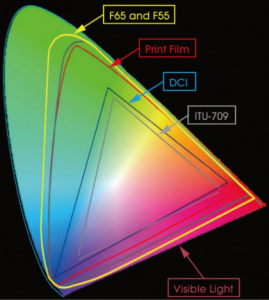
Anyway…. Perhaps you have seen a chart or diagram that looks like the one below before.
Sony colour gamuts.
Now this shows several things. The big outer oval shape is what is considered to be the equivalent to what we can see with our own eyes. Within that range are triangles that represent the boundaries of different colour gamuts or colour ranges. The grey coloured triangle for example is REC-709.
Something useful to know is that the 3 corners of each of the triangles are whats referred to as the “primaries”. You will hear this term a lot when people talk about colour spaces because if you know where the primaries (corners) are, by joining them together you can find the size of the colour space or Gamut and what the colour response will be.
Look closely at the chart. Look at the shades of red, green or blue shown at the primaries for the REC-709 triangle. Now compare these with the shades shown at the primaries for the much larger F65 and F55 primaries. Is there much difference? Well no, not really. Can you figure out why there is so little difference?
Think about it for a moment, what type of display device are you looking at this chart on? It’s most likely a computer display of some kind and the Gamut of most computer displays is the same size as that of REC-709. So given that the display device your looking at the chart on can’t actually show any of the extended colours outside of the grey triangle anyway, is it really any surprise that you can’t see much of a difference between the 709 primaries and the F65 and F55 primaries. That’s the problems with charts like this, they don’t really tell you everything that’s going on. It does however tell us some things. Lets have a look at another chart:
SGamuts Compared.
This chart is similar to the first one we looked at, but without the pretty colours. Blue is bottom left, Red is to the right and green top left.
What we are interested in here is the relationship between the different colour space triangles. Using the REC-709 triangle as our reference (as that’s the type of display most TV and video productions will be shown on) look at how S-Gamut and S-Gamut3 is much larger than 709. So S-Gamut will be able to record deeper, richer colours than 709 can ever hope to show. In addition, also note how S-Gamut isn’t just a bigger triangle, but it’s also twisted and distorted relative to 709. This is really important.
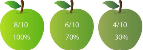
You may also want to refer to the top diagram as well as I do my best to explain this. The center of the overall gamut is white. As you draw a line out from the center towards the colour spaces primary the colour becomes more saturated (vivid). The position of the primary determines the exact hue or tone represented. Lets just consider green for the moment and lets pretend we are shooting a shot with 3 green apples. These apples have different amounts of green. The most vivid of the 3 apples has 8/10ths of what we can possibly see, the middle one 6/10ths and the least colourful one 4/10ths. The image below represents what the apples would look like to us if we saw them with our eyes.
The apples as we would see them with our own eyes.
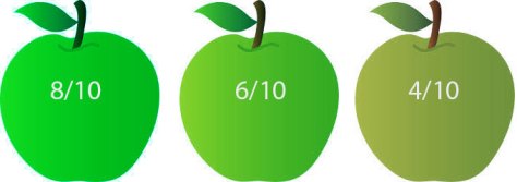
If we were shooting with a camera designed to match the 709 display specification, which is often a good idea as we want the colours to look right on the TV, the the greenest, deepest green we can capture is the 709 green primary. lets consider the 709 green primary to be 6/10ths with 10/10ths being the greenest thing a human being can see. 6/10ths green will be recorded at our peak green recording level so that when we play back on a 709 TV it will display the greenest the most intense green that the display panel is capable of. So if we shoot the apples with a 709 compatible camera, 6/10ths green will be recorded at 100% as this is the richest green we can record (these are not real levels, I’m just using them to illustrate the principles involved) and this below is what the apples would look like on the TV screen.
6/10ths Green and above recorded at 100% (our imaginary rec-709)
So that’s rec-709, our 6/10ths green apple recorded at 100%. Everything above 6/10 will also be 100% so the 8/10th and 6/10ths green apples will look more or less the same.
What happens then if we record with a bigger Gamut. Lets say that the green primary for S-Gamut is 8/10ths of visible green. Now when recording this more vibrant 8/10ths green in S-Gamut it will be recorded at 100% because this is the most vibrant green that S-Gamut can record and everything less than 8/10 will be recorded at a lower percentage.
But what happens if we play back S-Gamut on a 709 display? Well when the 709 display sees that 100% signal it will show 6/10ths green, a paler less vibrant shade of green than the 8/10ths shade the camera captured because 6/10ths is the most vibrant green the display is capable of. All of our colours will be paler and less rich than they should be.
The apples recorded using a big gamut but displayed using 709 gamut.
So that’s the first issue when shooting with a larger colour Gamut than the Gamut of the display device, the saturation will be incorrect, a dark green apple will be pale green. OK, that doesn’t sound like too big a problem, why don’t we just boost the saturation of the image in post production? Well if the display is already showing our 100% green S-Gamut signal at the maximum it can show (6/10ths for Rec-709) then boosting the saturation won’t help colours that are already at the limit of what the display can show simply because it isn’t capable of showing them any greener than they already look. Boosting the saturation will make those colours not at the limit of the display technology richer, but those already at the limit won’t get any more colourful. So as we boost the saturation any pale green apples become greener while the deep green apples stay the same so we loose colour contrast between the pale and deep green apples. The end result is an image that doesn’t really look any different that it would have done if shot in Rec-709.
Saturation boosted S-Gamut looks little different to 709 original.Sony colour gamuts.
But, it’s even worse that just a difference to the saturation. Look at the triangles again and compare 709 with S-Gamut. Look at how much more green there is within the S-Gamut colour soace than the 709 colour space compared to red or blue. So what do you think will happen if we try to take that S-Gamut range and squeeze it in to the 709 range? Well there will be a distinct colour shift towards green as we have a greater percentage of green in S-Gamut than we should have in Rec-709 and that will generate a noticeable colour shift and the skewing of colours.
Squeezing S-Gamut into 709 will result in a colour shift.
This is where Sony have been very clever with S-Gamut3. If you do take S-Gamut and squeeze it in to 709 then you will see a colour shift (as well as the saturation shift discussed earlier). But with S-Gamut3 Sony have altered the colour sampling within the colour space so that there is a better match between 709 and S-Gamut3. This means that when you squeeze S-Gamut3 into 709 there is virtually no colour shift. However S-Gamut3 is still a very big colour space so to correctly use it in a 709 environment you really need to use a Look Up Table (LUT) to re-map it into the smaller space without an appreciable saturation loss, mapping the colours in such a way that a dark green apple will still look darker green than a light green apple but keeping within the boundaries of what a 709 display can show.
Taking this one step further, realising that there are very few, if any display devices that can actually show a gamut as large as S-Gamut or S-Gamut3, Sony have developed a smaller Gamut known as S-Gamut3.cine that is a subset of S-Gamut3.
The benefit of this smaller gamut is that the red green and blue ratios are very close to 709. If you look at the triangles you can see that S-Gamut3.cine is more or less just a larger version of the 709 triangle. This means that colours shifts are almost totally eliminated making this gammut much easier to work with in post production. It’s still a large gamut, bigger than the DCI-P3 specification for digital cinema, so it still has a bigger colour range than we can ever normally hope to see, but as it is better aligned to both P3 and rec-709 colourists will find it much easier to work with. For productions that will end up as DCI-P3 a slight saturation boost is all that will be needed in many cases.
So as you can see, having a huge Gamut may not always be beneficial as often we don’t have any way to show it and simply adding more saturation to a seemingly de-saturated big gamut image may actually reduce the colour contrast as our already fully saturated objects, limited by what a 709 display can show, can’t get any more saturated. In addition a gamut such as S-Gamut that has a very different ratio of R, G and B to that of 709 will introduce colour shifts if it isn’t correctly re-mapped. This is why Sony developed S-Gamut3.cine, a big but not excessively large colour space that lines up well with both DCI-P3 and Rec-709 and is thus easier to handle in post production.
A little while back I took the opportunity to run some tests during the CML camera assessments at UWE Bristol with the Sony PMW-F55 and both the 4K and 2K Optical Low Pass Filters. The results were largely as expected, but I didn’t have the time until now to share those results, so here they are.
I shot two different series of test shots. The first series are of a resolution test chart, the second set of the model that was on set, in order to asses the impact on skin tones etc. It should be noted that the resolution chart did not have patterns that can show 4K resolution, really what I was looking for was aliasing and other image undesirable artefacts.
What’s the 2K OLPF filter for?
When the PMW-F5 and PMW-F55 are shooting at high speeds above 70fps the camera sensor is read as a 2K sensor instead of the normal 4K. There are two ways that this can occur. 2K Full Sensor Scan and Center Crop 2K.
Full Scan 2K uses the entire sensor but now the sensor is read as a 2K sensor instead of a 4K sensor. The camera is fitted with a 4K optical low pass filter (OLPF) at the factory. However when shooting using 2K full scan the 4K filter is ineffective and needs to be replaced with a 2K OLPF. Fortunately Sony made the OLPF on the F5/F55 interchangeable and an optional 2K filter can be purchased from Sony. It takes just a couple of minutes to swap the filters.
The 2K OLPF is also required when shooting in 2K raw when the Sensor Scan in the cameras “Base Settings” is set to 2K Full Frame (2KFF).
Another possible application for the 2K OLPF is to soften the pictures a bit when shooting in 4K. If you find the 4K images with the 4K OLPF too sharp you can use the 2K OLPF to provide a softer, creamier look. Unlike a soft effect filter in front of the camera lens a filter behind the lens is not effected by changes in aperture of focal length, so the results are highly consistent.
On to the tests.
Click on any of the images to enlarge them and see the full size 4K images. NOTE THAT YOU MAY SEE ALIASING THAT ISN”T IN THE TRUE IMAGE WHEN VIEWING A SCALED IMAGE ON YOUR COMPUTER SCREEN, SO PLEASE VIEW WITH 1:1 PIXELS.
4K OLPF, shooting 2K Full Frame.
The first test was to see what happens when you shoot using 2K Full Frame with the standard 4K filter. Really there is no surprise here. Because the factory fitted 4K OLPF is ineffective at 2K you will get a lot of aliasing and moiré as can be seen by the rainbow patterns on the test chart.
So what happens if you swap the 4K OLPF for the 2K OLPF while shooting in 2K Full Frame? Well all the unwanted aliasing simply goes away and you have a nice artefact free image.
2K OLPF, 2K Full Frame
So it’s easy enough to see that if you want to shoot 2K Full Frame, whether for slow motion or for 2K raw you really do need the 2K OLPF option.
But what about when shooting 4K Full Frame, how does the OLPF effect the sharpness of the image. Below are both the full frame, frame grabs plus a couple of crops of the girl so you can see how skin tones are effected.
4K OLPF shooting 4K Full Frame (crop)2K OLPF shooting 4K Full Frame (crop of original).
Notice how the shot done with the 2K OLPF is noticeably softer, the texture in her hair is softer, her skin looks smoother, yet the difference between the two images is not really that great. The 2K OLPF does not excessively blur the image, but it does give it a pleasing softness. This could be beneficial for cosmetics or fashion shoots, dream sequences etc. However it is also possible to soften footage in post production to produce a similar effect. Below are the full frame originals if you want to see the entire shot.
4K OLPF shooting 4K Full Frame.2K OLPF shooting 4K Full Frame.
One thing that you definitely don’t want to do is to accidentally use the 2K OLPF when you are shooting in any of the center scan modes. Remember that in center scan mode the sensor is still in effect a 4K sensor, just now you are only reading out a smaller 2K section from the center of the 4K sensor. As a result the 4K OLPF is still optimum. Below are some further crops from the whole image just shown the center of the test chart. Starting with 4K full frame scan using the 4K OLPF, which is beautifully sharp and clear.
4K OLPF shooting 4K Full Frame.
Next is with the 4K OLPF in 2K crop mode. The lens was changed to give a similar field of view.
4K OLPF Shooting 2K center scan mode.
It’s not really that surprising that the image is a little softer, the first image is part of a 4K image while this is from a 2K image, so it is lower resolution. There is some coloured moiré in this image, probably a result of changing the the lens, perhaps this lens is slightly sharper than the original lens so has greater resolving power. It is almost impossible to entirely eliminate coloured moiré with a bayer sensor and a chart like this will show it up, it’s a very tough test for a sensor. But compare this to a similar section of the shot done with the 4K OLPF with the camera shooting in 2K full frame scan mode and you can see that actually the moiré isn’t actually all that bad. In most real world applications you are not going to see the aliasing above unless you have a very very fine, in focus, repeating pattern similar to the one on the chart:
4K OLPF shooting 2K full frame scan mode. Really bad aliasing!
But what about using the 2K OLPF in 2K center scan mode, well take a look at how soft the image is. It just looks completely blurred and soft.
2K OLPF in 2K center scan mode. Very, very soft and blurry.
You really don’t want to shoot like this your pictures will look very soft indeed.
So there you have it. The 2K OLPF really is needed if you want to avoid heavy aliasing and moiré when shooting in any of the 2K Full Scan modes. You can also use it if you want to soften your 4K images a little for a smoother creamier look. But you definately don’t want to use the 2K OLPF in combination with any of the sensor center scan modes.
Here is the latest version of my PMW-F5 and PMW-F55 quick reference PDF guide. This will be updated and exapnded on a regular basis so please bookmark this page: https://www.xdcam-user.com/2014/04/pmw-f5-and-pmw…eference-guide/ so you can come back to download the latest version.
Please do let me know of any errors or omissions and anything else you would like to see added. Feel free to share and distribute the document, but note that a lot of work has gone into this and it is copyright, so hand it out, give it away, but don’t sell it and don’t remove the copyright notices or links.
I’ve been using various shoulder mounts for my F5 over the last year. They have all worked well for me. But at CabSat in Dubai I was lent a Vocas shoulder mount and handles to use with one of the F55’s I was using on the Sony booth.
Now, I’ve come across Vocas many, many times before, they are not new players in this arena and thier products have always looked to be well thought out and well made, but when I put the F55 rig on my shoulder and my hands wrapped around the beautifully carved wooden handles I just fell in love with it. When you use a camera day-in, day-out, how it feels in your hands or on your shoulder is really important and it’s amazing how a great shoulder rig can make using a camera a much more enjoyable experience. A bad rig will make using the camera a miserable chore.
Another view of my Vocas F5 rig.
So what is it about the Vocas rig I like so much? First of all it’s a fully modular system so you can buy just the bits you want or need. Many of the parts will work with other systems. Initially I just got the shoulder mount and hand grips, but after using these for a short while I realised I also wanted to replace the existing top plate and somewhat uncomfortable carry handle that I had been using with the Vocas one, so I added the top cheese plate and carry handle to my rig this week.
One of the delightful to hold Vocas wooden hand grips.
The thing that got my attention when I borrowed the rig back in March was the comfort of the handles. The carved wooden hand grips were developed in association with Cam-A-Lot, one of the larger high end cinematography rental houses in Europe. So they know their stuff and know what camera operators want. The design is simple but beautifully executed, a carefully shaped handgrip with an Arri style rosette. The top of the grip has a notch/extension that your thumb wraps around making your grip really secure, this won’t slip out of your hands by mistake. You don’t have to hang on to these handles, your grip is secure even with very light pressure. Your fingers wrap around smooth grooves in the front of the grip and it’s hard to explain, but it just “feels right” and wood is much nicer to hold than plastic or rubber (Vocas also make leather hand grips).
The hand grips are then attached to some extension arms and these arms then attach to the base plate. Again the design of the arms is really simple, but sometimes simple is really effective and these arms are really really light, yet very, very stiff, the quality and finish of the alloy used is excellent. You can join any Vocas arm to any other Vocas arm to create different angles and lengths and there is a range of different arms of various lengths and offsets to choose from. I’ve ended up with one short straight arm and one longer offset arm. Using these two arms I can configure the rig several ways.
A single Vocas hand grip on a short arm used to create an ENG style rig.
Using just the short arm I can place the right hand grip up alongside the lens for a very secure and very comfortable single handed ENG style shooting rig. There is no need for the strap that you have on the hand grip of an ENG lens. The wooden grips are so easy to grasp and so secure that you just don’t need that extra strap around the back of your hand. I could use the longer offset arm, mounted on the right side and offset to the left to place the hand grip under the lens for an alternative single handed rig.
Two handed configuration with two Vocas grips and arms.
By using the short arm on the right, angled down and the longer offset arm on the right angled down I can create a two handed rig. One thing I did find is that if you mount the single arm sections that I have on the rosettes on the shoulder mount the handles are quite close to your body. If you prefer your hand grips a little further away from your body you have a couple of options. Either double up on the arms joining two together to make a longer articulated arm, or do as I did and add the 15mm rail bracket that has a rosette at each end to mount the handles from the rods (Vocas also do a 19mm system). The rail bracket has a very neat quick release catch, so it’s a breeze to fit.
Underside of the Vocas PMW-F55 base plate.
But what about the shoulder mount that all this is hanging from? The one I have is the Vocas standard PMW-F5 and F55 base plate. Now, this doesn’t look anything special, but looks can be deceiving. This very comfortable base plate weighs only 600g. That’s quite a lot lighter than my previous base plates and lighter than the Sony equivalent. It’s a VCT-14 compatible plate so snaps in and out of the very common Sony quick release plate quickly and easily. If you don’t want VCT-14 compatibility the silver part with the VCT wedge in the picture above can be replaced with a flat plate for mounting directly on to tripods or other mounting systems.
The base plate can be slid forwards and backwards relative to the camera body to help you achieve perfect balance. The mounting screws run in a slot with deep shoulders that make the plate very ridged and secure. The comfortable soft shoulder pad can also be moved forwards and backwards within the base plate giving you further flexibility. On the sides of the base plate are a pair of Arri style rosettes and at both the front and rear there are holes for the usual 15mm rods.
Moving on to the top of the camera….. The comfort of the carry handle is so important, especially when the camera is rigged up with weighty accessories and heavy batteries. The last thing you want is blisters on your hands from a bad handle. So after experiencing the comfort of the hand grips I decided to add the Vocas top cheese plate and handle.
The Vocas handle and top cheese plate for the F5 and F55.
The handle has a very nice wooden grip insert which makes the camera very comfortable to carry. You also get a pair of posts to take a standard Sony shoulder strap. Oh Joy! Sony take note: please include provision for a shoulder strap on all your cameras, they are very useful! The top cheese plate is well… a cheese plate with lots of mounting holes for all your accessories. It’s very slightly raised from the top of the camera body to avoid inhibiting any cooling of the camera. The handle takes a mounting bush for the F5/F55 viewfinder that can be placed either at the front of the handle or on the rear. This is handy for film style shooting from behind the camera rather than to the side. You can also use a pair of 15mm rods attached to the handle that run above your lens if you need to mount a Matte Box from above or add extra items like follow focus motors. Integrated into the handle is a pair of cold shoes for accessories such as a camera light. If you have a very heavy lens, like perhaps the new Canon 17-120mm or a Cabrio then the handle can be mounted facing forwards to get better balance.
Vocas side cheese plate that protects the viewfinder connector.
The last part of the kit is the optional side cheese plate. This serves two purposes. The main one for me is to protect the rather vulnerable viewfinder connector that sticks straight out from the side of the camera body. With a list price of just 95 Euros, this is a really wise investment (if you don’t use a cheese plate etc why not get one of my plastic viewfinder connector protectors that I sell on ebay). The other purpose is to provide yet more 1/4″ threaded mounting points on the side of the camera. I think it also looks cool! A small observation is that the rather flimsy connector still protrudes beyond the cheese plate by about 15mm, so bash it into a door frame walking through the door way and you could still damage the end of the connector. So I’m going to add a 1/4″ bolt to one of the threaded holes in front of the connector. This will stick out a bit and further protect the connector from damage.
So while a shoulder rig might not be the most interesting part of your camera kit, it is one of the most important. It’s what connects you to your camera, or what connects your camera to your tripod. If it isn’t comfortable, your camera will feel awkward. A bad rig might compromise your shots or shooting style, so getting the right rig is important and I can highly recommend Vocas as a supplier of shoulder rigs and associated support equipment. If you get the opportunity, do try the wooden hand grips. They are a bit more expensive than most plastic or rubber based hand grips, but they are just so nice to hold. Using this rig is a delight, I love my PMW-F5 and this rig makes it very easy and comfortable to use.
FYI. The Matte Box is one of the new Alphatron Matte Boxes. A review of which will be on-line very soon. It’s nice! The follow focus is an Alphatron ProPull, a great little compact follow focus with adjustable end stops for fast focus pulls. The lens is a Samyang Cine Prime. Based on a DSLR lens but with pitch gears and smooth aperture adjustment. Great image quality and T1.5.
It’s been brought to my attention that there is a lot of concern about the apparent noise levels when using Sony’s new Slog3 gamma curve. The problem being that when you view the ungraded Slog3 it appears to have more noise in the shadows than Slog2. Many are concerned that this “extra” noise will end up making the final pictures nosier. The reality is that this is not the case, you won’t get any extra noise using Slog3 over Slog2. Because S-Log3 is closer to the log gamma curves used in other cameras many people find that Slog3 is generally easier to grade and work with in post production.
So what’s going on?
Slog3 mimics the Cineon Log curve, a curve that was originally designed, back in the 1980’s to match the density of film stocks. As a result the shadow and low key parts of the scene are shown and recorded at a brighter level than Slog2. S-Log2 was designed from the outset to work with electronic sensors and is optimised for the way an electronic sensor works rather than film. Because the S-Log3 shadow range has more gain than S-log2, the shadows end up a bit brighter than it perhaps they really needs to be and because of the extra gain the noise in the shadows appears to be worse. The noise level might be a bit higher but the important thing, the ratio between wanted picture information and un wanted noise is exactly the same whether in Slog2 or Slog3.
Let me explain:
The signal to noise ratio of a camera is determined predominantly by the sensor itself and how the sensor is read. This is NOT changing between gamma curves.
The other thing that effects the signal to noise ratio is the exposure level, or to be more precise the aperture and how much light falls on the sensor. This should be same for Slog2 and Slog3. So again no change there.
As these two key factors do not change when you switch between Slog2 and slog3, there is no change in the signal to noise ratio between Slog2 and Slog3. It is the ratio between wanted picture information and noise that is important. Not the noise level, but the ratio. What people see when they look at ungraded SLog3 is a higher noise level simply because ALL the signal levels are also higher, both noise and desirable image information. So the ratio between the wanted signal and the noise is actually no different for both Slog2 and Slog3.
Gamma is just gain, nothing more, nothing less, just applied by variable amounts at different levels. In the case of log, the amount of gain decreases as you go further up the curve.
Increasing or decreasing gain does NOT significantly change the signal to noise ratio of a digital camera (or any other digital system). It might make noise more visible if you are amplifying the image more than normal in an underexposure situation where you are using that extra gain to compensate for not enough light. But the ratio between the dark object and the noise does not change, it’s just that as you have made the dark object brighter by adding gain, you have also made the noise brighter by the same amount, so the noise also becomes brighter and thus more obvious.
Lets take a look at some Math. I’ll keep it very simple, I promise!
Just for a moment to keep things simple, lets say some camera has a signal to noise ratio of 3:1 (SNR is normally measured in db, but I’m going to keep things really simple here).
So, from the sensor if my picture signal is 3 then my noise will be 1.
If I apply Gamma Curve “A” which has 2x gain then my picture becomes 6 and my noise becomes 2. The SNR is 6:2 = 3:1
If I apply Gamma Curve “B” which has 3x gain then my picture becomes 9 and my noise becomes 3. The SNR is 9:3 = 3:1 so no change to the ratio, but the noise is now 3 with gamma B compared to Gamma A where it is 2, so the gamma B image will appear at first glance to be noisier.
Now we take those imaginary clips in to post production:
In post we want to grade the shots so that we end up with the same brightness of image, so lets say our target level after grading is 12.
For the gamma “A” signal we need to add 3x gain to take 6 to 18. As a result the noise now becomes 6 (3 x 2 = 6).
For the gamma “B” signal (our noisy looking one) we need to use less gain in post, only 2x gain, to take 9 to 18. When we apply 2x gain our noise for gamma B becomes 6 (2 x 3 = 6).
Notice anything? In both cases the noise in the final image is exactly the same, in both cases the final image level is 18 and the final noise level is 6, even though the two recordings started at different levels with one appearing noisier than the other.
OK, so that’s the theory, what about in practice?
Take a look at the images below. These are 400% crops from larger frames. Identical exposure, workflow and processing for each. You will see the original Slog2 and SLog3 plus the Slog 2 and Slog 3 after applying the LC-709 LUT to each in Sony’s raw viewer. Nothing else has been done to the clips. You can “see” more noise in the raised shadows in the untouched SLog3, but after applying the LUTs the noise levels are the same. This is because the Signal to Noise ratio of both curves is the same and after adding the LUT’s the total gain applied (camera gain + LUT gain) to get the same output levels is the same.
It’s interesting to note in these frame grabs that you can actually see that in fact the S-Log3 final image looks if anything a touch less noisy. The bobbles and the edge of the picture frame look better in the Slog3 in my opinion. This is probably because the S-Log3 recording uses very slightly higher levels in the shadow areas and this helps reduce compression artefacts.
The best way to alter the SNR of a typical video system (other than through electronic noise reduction) is by changing the exposure, which is why EI (Exposure Index) and exposure offsets are so important and so effective.
Slog3 has a near straight line curve above middle grey. This means that in post production it’s easier to grade as adjustments to one part of the image will have a similar effect to other parts of the image. It’s also very, very close to Cineon and to Arri Log C and in many cases LUT and grades designed for these gammas will also work pretty well with SLog3.
The down side to Slog3?
Very few really. Fewer data points are recorded for each stop in the brighter parts of the picture and highlight range compared to Slog2. This doesn’t change the dynamic range but if you are using a less than ideal 8 bit codec you may find S-Log2 less prone to banding in the sky or other gradients compared to S-Log3. With a 10 bit recording, in a decent workflow, it makes very little difference.
Storm chasing season is on the way and I will be off to the USA to shoot landscapes, storms and maybe tornadoes in May. If you fancy a bit of an adventure and want to shoot stuff like this why not join me? See this link for more info. In the mean time why not take a look at this extended and re-graded version of the Supercell storm video I shot last May. It’s on YouTube in 4K if you select “2160” as the image size. Just wish YouTube wouldn’t compress stuff so much.
This guide to Cine-EI is based on my own experience with the Sony PMW-F5 and F55. There are other methods of using LUT’s and CineEI. The method I describe below, to the best of my knowledge, follows standard industry practice for working with a camera that uses EI gain and LUT’s.
If you find the guide useful, please consider buying me a beer or a coffee. It took quite a while to prepare this guide and writing can be thirsty work.
If you want you can download this guide as a PDF by clicking on this link: Ultimate Guide to CineEI on the PMW. I’d really appreciate a drink if your going to take away the PDF.
In this guide I hope to help you get the very best from the Cine EI mode on Sony’s PMW-F5 and PMW-F55 cameras. The cameras have two very distinct shooting mode, Cine EI and Custom Mode. In custom mode the camera behaves much like any other traditional video camera where what you see in the viewfinder is what’s recorded on the cards. In custom mode you can change many of the cameras settings such as gamma, matrix, sharpness to create the look you are after in-camera. “Baking-in” the look of your image in camera is great for content that will go direct to air or for fast turn around productions. But a baked-in look can be difficult to alter in post production. In addition it is very hard to squeeze every last drop of picture information in to the recordings in this mode.
The other mode, Cine-EI, is primarily designed to allow you to record as much information about the scene as possible. The footage from the camera becoming in effect a “digital negative” that can then be developed in post and the final highly polished look of the film or video created. In addition the Cine-EI mode mimics the way a film camera works giving the cinematographer the ability to rate the camera at different ISO’s to those specified by Sony. This can be used to alter the noise levels in the footage or to help deal with difficult lighting situations.
One further “non-standard” way to use Cine-EI is to use a LUT (Look Up Table) to create an in-camera look that can be baked in to the footage while you shoot. This offers an alternative to custom mode. Some users will find it easier to create a specific look for the camera using a LUT than they would by adjusting camera settings such as gamma and matrix.
MLUT’s, LUT’s and LOOK’s (all types of Look Up Tables) are only available in the Cine-EI mode.
THE SIMPLIFIED VERSION:
Before I go through all the “why’” and “hows” first of all let me just say that actually CineEI is easy. I’ve gone in to a lot of extra detail here so that you can full master the mode and the concepts behind it.
But in it’s simplest form, all you need to do is to turn on the MLUT’s. Choose the MLUT that you like the look of, or is closest to the final look you are after. Expose so that the picture in the viewfinder or on your monitor looks how you want and away you go.
Then in post production bring in your Slog footage. Apply the same LUT as you used when you shot and the footage will look as shot, only as the underlying footage is either raw or Slog you have a huge range of adjustment available to you in post.
THAT’S IT! If you want, it’s that simple.
If you want to get fancy you can create your own LUT and that’s really easy too (see the end of the document). If you want less noise in your pictures use a lower EI. I shoot using 800EI on my F5 and 640EI on the F55 almost all the time.
Got an issue with a very bright scene and strong highlights, shoot with a high EI.
Again, it’s really simple.
But anyway, lets learn all about it and why it works the way it works.
LATITUDE AND SENSITIVITY.
The latitude and sensitivity of the F5/F55, like most cameras is primarily governed by the latitude and sensitivity of the sensor. The latitude of the sensor in these cameras is around 14 stops. Adding different amounts of conventional camera gain or using different ISO’s does not alter the sensors actual sensitivity to light, only how much the signal from the sensor is amplified. Like turning up or down the volume on a radio, the sound level gets higher or lower, but the strength of the radio signal is just the same. Turn it up loud and not only does the music get louder but also any hiss or noise, the ratio of signal to noise does not change, they BOTH get louder. Turn it up too loud and it will distort. If you don’t turn it up loud enough, you can’t hear it, but the radio signal itself does not change. It’s the same with the cameras sensor. It always has the same sensitivity, but with a conventional camera we can add or take away gain (volume control?) to make the pictures brighter or darker (louder?).
NATIVE ISO:
Sony’s native ISO ratings for the cameras, 1250ISO for the F55 and 2000ISO for the F5 are values chosen by Sony that give a good trade off between sensitivity, noise and over/under exposure latitude. In general these native ISO’s will give excellent results. But there may be situations where you want or need different performance. For example you might prefer to trade off a little bit of over exposure headroom for a better signal to noise ratio, giving a cleaner picture. Or you might need a very large amount of over exposure headroom to deal with a a scene with lots of bright highlights.
The Cine EI mode allows you to change the effective ISO rating of the camera.
With film stocks the manufacturer will determine the sensitivity of the film and give it an Exposure Index which is normally the equivalent of the films measured ASA/ISO. It is possible for a skilled cinematographer to rate the film stock with a higher or lower ISO than the manufacturers rating to vary the look or compensate for filters and other factors. You then adjust the film developing and processing to give a correctly exposed looking image. This is a common tool used by cinematographers to modify the look of the film, but the film stock itself does not actually change it’s base sensitivity, it’s still the same film stock with the same base ASA/ISO.
Sony’s Cine EI and EI modes on Red and Alexa are very similar. While it has many similarities to adding conventional video camera gain, the outcome and effect can be quite different. If you have not used it before it can be a little confusing, but once you understand the way it works it is very useful and a great way to shoot. Again, remember that the actual sensitivity of the sensor itself never changes.
CONVENTIONAL VIDEO CAMERA GAIN.
Increasing conventional camera gain will reduce the cameras dynamic range as something that is recorded at maximum brightness (109%) at the native ISO would be pushed up above the peak recording level and into clipping if the conventional camera gain was increased because we can’t record a signal larger than 109%. But as the true sensitivity of the sensor does not change, the darkest object the camera can actually detect remains the same. Dark objects may appear a bit brighter, but there is still a finite limit to how dark an object the camera can actually see and this is governed by the sensors noise floor and signal to noise ratio (from the sensors own background noise). Any very dark picture information will be hidden in the sensors noise. Adding gain will bring up both the noise and darkest picture information, so anything hidden in the noise at the native ISO (or 0db) will still be hidden in the noise at a higher gain or ISO as both the noise and small signal are amplified by the same amount.
Using negative conventional gain or going lower than the native ISO may also reduce dynamic range as picture information very close to black may be shifted down below black when you subtract gain or lower the ISO. At the same time there is a limit to how much light the sensor can deal with before the sensor itself overloads. So even though reducing the ISO or gain may make the picture darker, the sensor clipping/overload point remains the same, so there is no change to the upper dynamic range, just a reduction in recording level.
As Sony’s Slog2 and Slog3 are tailored to capture the cameras full 14 stop range this means that when shooting with Slog2 or Slog3 the gamma curve will only work as designed and deliver the maximum dynamic range when the camera is at it’s native ISO. At any other recording ISO or gain level the dynamic range will be reduced. IE: If you were to use SLog2 or SLog3 with the camera in custom mode and not use the native ISO by adding gain or changing the ISO, you will not get the full 14 stop range that the camera is capable of delivering.
EXPOSURE LEVELS FOR DIFFERENT GAMMA CURVES AND CONTRAST RANGES.
It’s important to know (or better still understand) that different gamma curves with different contrast ranges will require different exposure levels. The TV system that we use today is currently based around a standard known as Rec-709. This standard specifies the contrast range that a TV set or monitor can show and which recording levels represent which display brightness levels. Most tradition TV cameras are also based on this standard. Rec-709 does have some serious restrictions, the brightness and contrast range is very limited as these standards are based around TV standards and technologies developed 50 years ago. To get around this issue most TV cameras use methods such as a “knee” to compress together some of the brighter part of the scene into a very small recording range.
A traditional TV camera with a limited dynamic range compresses only a small highlight range.
As you can see in the illustration above only a very small part of the recording “bucket” is used to hold a moderately large compressed highlight range. In addition a typical TV camera can’t capture all of the range in many scenes anyway. The most important parts of the scene from black to white is captured more or less “as is”. This leaves just a tiny bit of space above white to squeeze in a few highly compressed highlights. The signal from the TV camera is then passed directly to the TV and as the shadows, mid range and skin tones etc are all at more or less the same level as captured the bulk of scene looks OK on the TV/Monitor. Highlights may look a little “electronic” due to the very large amount of compression used.
But what happens if we want to record more of the scenes range? As the size of the recording “bucket”, the codec etc, does not change, in order to capture a greater range and fit it in to the same space, we have to re-distribute how we record things.
Recording a greater dynamic range into the same sized bucket.
Above you can see that instead of just compressing a small part of the highlights we are now capturing the full dynamic range of the scene. To do this we have altered the levels that everything is recorded at. Blacks and shadows are a little lower, greys and mids are a fair bit lower and white is a lot lower. By bringing all these levels down we make room for the highlights and the really bright stuff to be recorded without being excessively compressed.
The problem with this though is that when you output the picture to a monitor or TV it looks odd. It will lack contrast as the really bright stuff is displayed at the same brightness as the conventional 709 highlights. White is now only as bright as faces would be with a conventional TV camera and Faces are only a little bit above the middle grey level.
This is how Slog works. By re-distributing the recording levels we can squeeze a much bigger dynamic range into the same size recording bucket. But it won’t look quite right when viewed directly on a standard TV or monitor. It may look dark and certainly a bit washed out.
I hope you can also see from this that whenever the cameras gamma curve does not match that of the TV/Monitor the picture might not look quite right. Even when correctly exposed white may be at different levels, depending on the gamma being used, especially if the gamma curve has a greater range than the normal Rec-709 used in old school TV cameras.
THE CORRECT EXPOSURE LEVELS FOR SLOG-2 and SLOG-3.
Lets look at the correct exposure levels for SLog-2 and SLog-3. As these gamma curves have a very large dynamic range the recording levels that they use are different to the levels used by the normal 709 gamma curve used for conventional TV. As a result when correctly exposed, Slog looks dark and low contrast on a conventional monitor or in the viewfinder. The table below has the correct levels for middle grey and 90% reflectance white for the different types of Slog.
Correct exposure levels for Sony’s Slog.
The white level in particular is a lot lower than we would normally use for TV gamma. This is done to make extra space above white to fit in the extended range that the camera is capable of capturing, all those bright highlights, bright sky and clouds and other things that cameras with a smaller dynamic range struggle to capture.
Let’s now take a look at how to set the correct starting point exposure for SLog-3. You can use a light meter if you wish, but if you do want to use a light meter I would first suggest you check the calibration of the light meter by using the grey card method below and comparing the what the light meter tells you with the results you get with a grey or white card.
The most accurate method is to use a good quality grey card and a waveform display. For the screen shots seen here I used a Lastolite EzyBalance Calibration Card. This is a pop up grey card/white card that fits in a pocket but expands to about 30cm/1ft across giving a decent sized target. It has middle grey on one side and 90% reflectance white on the other. With the MLUT’s off, set the exposure so that the grey card is exposed at the appropriate level (see table above).
Note: To get the waveform to display you must have BOTH the SDI SUB and Viewfinder MLUT’s OFF or BOTH ON. The waveform is turned on and off under the “VF” – “Display ON/OFF” – “Video Signal Monitor” settings of the main menu. Sadly the cameras built in waveform display is not the best so it may help to use an external monitor with a better waveform display.
Setting the correct exposure for Slog-3 using a grey card. Middle Grey should be 41%
If you don’t have access to a better waveform display you can use a 90% reflectance white card and zebras. By setting up the Zebras with a narrow aperture window of around 3% you can get a very accurate exposure assessment for various shades of white. For SLog-3 set the Zebras to 3% aperture and the level at 61%. Sadly the zebras don’t go below 60%. For Slog-2 using 60% will be accurate enough, a 1% error is not going to do any real harm. You can use exactly the same method for S-Log2 just by using the SLog-2 levels detailed in the chart above.
Setting up the Zebras to measure S-Log3 exposure of white card (90% reflectance white card).Correct exposure for S-Log3 when using a 90% reflectance white target.
The image above shows the use of both the Zebras and Waveform to establish the correct exposure level for S-Log3 when using a 90% reflectance white card or similar target. Please note that very often a piece of white paper or a white car etc will be a little bit brighter than a calibrated 90% white card. If using typical bleached white printer paper I suggest you add around 4% to the white values in the above chart to prevent under exposure.
SO HOW DOES CINE-EI WORK?
Cine EI is selected in the Base Settings page. It works in YPbPr, RGB and Raw main operation modes.
Cine-EI (Exposure Index) works differently to conventional camera gain. It’s operation is similar in other cameras that use Cine-EI or EI gain such as the F5, F55, F3, F65, Red or Alexa. You enable Cine-EI mode in the camera menus Base Settings page. On the F5 and F55 it works in YPbPr, RGB and RAW modes.
IMPORTANT: In the Cine-EI mode the ISO of the recordings remains fixed at the cameras native ISO (unless baking in a LUT, more on that later). By always recording at the cameras native ISO you will always have 14 stops of dynamic range.
YOU NEED TO USE A LUT:
Important: For Cine-EI mode to work as expected you should monitor your pictures in the viewfinder or via the SDI/HDMI output through one of the cameras built in MLUT’s (Look Up Table), LOOK’s or User3D LUT’s. So make sure you have the MLUT’s turned on. If you don’t have a LUT then it won’t work as expected because the EI gain is applied to the cameras LUT’s. At this stage just set the MLUT’s to on for the Sub&HDMI output and the Viewfinder out.
For CineEI to work correctly you MUST turn on the LUT’s for the Viewfinder and/or Sub&HDMI output.You can turn the MLUT’s on and off by pressing the CAMERA button until you see the MLUT controls, then use the hotkeys to turn the MLUT’s on and off.
EXPOSING VIA THE LUT/LOOK.
At the cameras native ISO (2000 on F5, 1250 on F55), when shooting via a LUT you should adjust your exposure so that the picture in the viewfinder looks correctly exposed. If the LUT is correctly exposed then so too will the S-log. As a point of reference, middle grey for Rec-709 and the 709(800) LUT should be at, or close to 42%.
This is really quite simple, generally speaking when using a LUT, if it looks right, it probably is right. However it is worth noting that different LUT’s may have slightly different optimum exposure levels. For example the 709(800) LUT is designed to be a very close match to the 709 gamma curve used in the majority of monitors, so this particular LUT is really simple to use because if the picture looks normal on the monitor then your exposure will also be normal.
Correct exposure of Middle Grey for the 709(800) MLUT. Middle Grey should be 42%. 90% will be 90%.Correct exposure of the 709(800) LUT using a 90% white card, white will be 90%. You can use zebras at 90% to check this level.
The above images show the correct exposure levels for the 709(800) LUT. Middle grey should be 42% and 90% white is… well 90%. Very simple and you can easily use zebras to check the white level by setting them to 90%. As middle grey is where it normally is on a TV or monitor and white is also where you would expect to see it, when using the 709(800) LUT, if the picture looks right in the viewfinder then it generally is right. This means that the 709(800) LUT is particularly well suited to being used to set exposure as a correctly exposed scene will look “normal” on a 709 TV or monitor.
Many of the other LUT’s and Looks however capture a contrast range that far exceeds the Rec-709 standard used in most monitors. So you may need to adjust your exposure levels slightly to allow for this.
The LC709-TypeA Look is very popular as a LUT for the PMW-F5 and F55 as it closely mimics the images you get from an Arri Alexa (“type A” = type Arri).
The “LC” part of the Look’s name means Low Contrast and this also means – big dynamic range. Whenever you take a big dynamic range (lots of shades) and show it on a display with a limited dynamic range (limited shades) all the shades in the image get squeezed together to fit into the monitors limited range and as a result the contrast gets reduced. This also means that middle grey and white are also squeezed closer together. With conventional 709 middle grey would be 42% and white around 80-90%, but with a high dynamic range/low Contrast gamma curve white gets squeezed closer to grey to make room for the extra dynamic range. This means that middle grey will remain close to 42% but white reduces to around 72%. So for the LC709 Looks in the F5/F55 optimum exposure is to have middle grey at 42% and white at 72%. Don’t worry too much if you don’t hit those exact numbers, a little bit either way does little harm.
Correct white level for the LC709 LOOK’s. White should be around 72%
RECOMMENDED LUT EXPOSURE LEVELS.
Here are some white levels for some of the built in LUT’s. The G40 or G33 part of the HG LUT’s is the recommended value for middle grey. Use these levels for the zebras if you want to check the correct exposure of a 90% reflectance white card. I have also include an approximate zebra value for a piece of typical white printer paper.
709(800) = Middle Grey 42%. 90% Reflectance white 90%, white paper 92%.
HG8009(G40) = Middle Grey 40%. 90% Reflectance white 83%, white paper 86%.
HG8009(G33) = Middle Grey 33%. 90% Reflectance white 75%, white paper 80%.
The “LC709” LOOK’s = Middle Grey 42%. 90% Reflectance white 72%, white paper 77%.
DONT PANIC if you don’t get these precise levels! I’m giving them to you here so you have a good starting point. A little bit either way will not hurt. Again, generally speaking if it looks right in the viewfinder or on your monitor screen, it is probably close enough not to worry about it.
If you ever need to confirm the correct levels for any given LUT or Look it’s really easy. Put the camera in to CineEI. Turn OFF the MLUT’s (remember you can turn LUT’s on and off from the cameras side information screen by pressing the CAMERA menu button until you see the LUT options at the bottom of the display). With the MLUT’s OFF use a grey card or white card (or maybe your calibrated light meter) to set the exposure for the Slog curve you have chosen.
Once you have established the correct exposure for the SLog, without adjusting anything else, turn on the MLUT’s, ensure the camera is at the native ISO and choose the LUT or LOOK that you want to check. Now you can measure the grey and white point for the LUT/Look you have chosen and see on the monitor or in the viewfinder what the correct exposure looks like via the LUT. It probably won’t be vastly different from normal 709 in most cases, especially middle grey this tends to stay very close to 42%, but it’s useful to do this check if you are at all unsure.
If you can, use a LUT, not a LOOK. That’s my recommendation, not a hard and fast rule but if you’re new to CineEI, LUT’s and Looks please read on as to why I say this. Otherwise skip on to Baking-in the LUT/LOOK.
I recommend that for exposure evaluation you should normally try to use one of the cameras built in MLUT’s not the LOOK’s. Especially if you are new to LUT’s and Looks. This is because the LUT’s behave differently to the Looks when you use a high or low EI.
I found that when you lower the EI gain, below native, the output level of the LOOK lowers, so that depending on the EI, the clipping, peak level and middle grey values are different. For example on my PMW-F5 at 500 EI the LC709TypeA LUT has a peak output (clipping) level of just 90% while at 2000 ISO it’s 98%. This also means that middle grey of the LOOK will shift down slightly as you lower the EI. This means that for consistent exposure at different low EI’s you may need to offset your exposure very slightly (it is only very slight). It also means that at Native EI if the waveform shows peak levels at 90% you are not overexposed or clipped, but at low EI’s 90% will mean clipped Slog, so beware of this peak level offset with the LOOK’s.
When you raise the EI of the LOOKS, the input clipping point of the Look profile changes. For each stop of EI you add the LOOK will clip one stop earlier than the underlying Slog. For example set the LC709TypeA LUT to 8000 ISO (on my PMW-F5) and the LOOK itself hard clips 2 stops before the actual SLog3 clips. So your LOOK will make it appear that your Slog is clipped up to 2 stops before it actually is and the dynamic range and contrast range of the LOOK varies depending on the EI, so again beware.
So, the Looks may give the impression that the Slog is clipped if you use a high ISO and will give the impression that you are not using your full available range at a low ISO. I suspect this is a limitation of 3D LUT tables which only work over a fixed 0 to1 input and output range.
What about the 1D LUT’s? Well the built in LUT’s don’t cover the full range of the Slog curves so you will never see all of your dynamic range at all at once. However I feel their behaviour at low and high EI’s is a little bit more intuitive than the level shifts and early clipping of the LOOKs.
The 1D LUT’s will always go to 109%. So there are no middle grey shifts for the LUT, no need to compensate at any ISO. In addition if you see any clipping below 109% then it means your SLog is clipping, for example if you set the camera to 500 ISO (on an F5), when you see the 709(800) LUT clipping at 105% it’s because the Slog is also clipping.
At High ISO’s you won’t see the top end of the SLog’s exposure range anyway because the 1D LUT’s range is less than Slog’s range, but the LUT itself does not clip, instead highlights just go up above 109% where you can’t see them and this in my opinion is more intuitive behaviour than the clipped LOOK’s that don’t ever quite reach 100% and clip at lower than 100% even when the Slog itself isn’t clipped.
At the end of the day use the ones that work best for you, just be aware of the limitations of both and that the LUT’s and LOOKs behave very differently. I suggest you test and try both before making any firm decisions, but my recommendation is to use the LUT’s rather than the LOOK’s when judging exposure.
Using the built in MLUT’s?
There are 5 built in MLUT’s: P1 709(800), P2 HG8009G40, P3 HG8009G33, P4 Slog2, P5 Slog3. You can only select the Slog2 LUT when the camera is set to SLog2 in the base settings, the same for the SLog3 LUT. You can also create your own 1D LUT’s in Sony’s Raw Viewer software and user 3D LOOK’s in most grading suites but that’s a whole other subject that I’m not going to cover right here (see this article for user 3D Look creation or go to the additional LUT creation section at the bottom of this document), for now lets just consider the built in LUT’s.
All 3 of the other built in LUTs have an 800% exposure range. The camera itself has a 1300% exposure range when your shooting in CineEI, Raw, SLog2 or SLog3 (1300% more than standard gamma). So if you want to see your full exposure range then you should select SLog as your LUT or turn the LUT’s off. However the pictures will be flat looking and lack contrast, which makes accurate focussing harder and you must set your exposure using the SLog levels given above, so in addition Slog 2 will look dark. Note that if you press the “camera” button by the side LCD screen 2 times you can use the hot keys around the LCD to change LUT and turn the LUT’s on and off.
If you use MLUT’s P1, P2 orP3 then the viewfinder pictures will have near “normal” contrast. Your exposure levels will be more normal looking (although P3 should have middle grey at 33% so should look a touch darker than normal) but you won’t be seeing the full recorded range, only 800% out of the possible 1300% is displayed, so some things might look clipped in the viewfinder while the actual recording is not. I suggest switching the LUT’s off momentarily to check this, or connect a second monitor to the Main SDI to monitor the non LUT output. Do note that if using Slog2/Slog3 as a LUT and at a positive EI ISO you won’t see your full recording range. You will still see up to a stop more than the 800% LUT’s but at high EI’s the Slog2 or Slog3 LUT will clip slightly before the camera recordings. At low EI’s the Slog LUT’s will clip at the same time as the camera, but the level of the clipping point on any waveform display via the LUT output will be lower and this can be a little confusing. Unfortunately if you turn off the LUT’s you can’t get the cameras built in waveform display. This is where an external monitor with waveform becomes very handy to monitor the non LUT native ISO Slog output from the main HDSDI output.
Personally I prefer to use the 709(800) LUT for exposure as the restricted range matches that of most consumer TV’s etc so I feel this gives me a better idea of how the image may end up looking on a consumers TV. The slightly restricted range will help highlight any contrast issue that may cause problems in post. It’s often easier to solve these issues when shooting rather than leaving it to later. Also I find my Slog exposure more accurate as the LUT’s restricted range means you are more likely to expose within finer limits. In addition as noted above I fell the LUT’s behaviour is more predictable and intuitive at high and low EI’s than the LOOK’s.
BAKING IN THE LUT/LOOK.
When shooting using a high or low EI, the EI gain is added or subtracted from the LUT or LOOK, this makes the picture in the viewfinder or monitor fed via the LUT brighter or darker depending on the EI used. In Cine-EI mode you want the camera to always actually record the raw and S-Log2/S-log3 at the cameras native ISO (1250 ISO for F55 or 2000 ISO for F5). So normally you want to leave the LUT’s OFF for the internal recording. Just in case you missed that very important point: normally you want to leave the LUT’s OFF for the internal recording!
Normally in CineEI you need to ensure that the LUT is OFF for the Main&Internal so that there is no LUT added to the SxS recordings.
Just about the only exceptions to this might be when shooting raw or when you want to deliberately record with the LUT/Look baked in to your SxS recordings. By “baked-in” I mean with the gamma, contrast and color of the LUT/Look permanently recorded as part of the recording. You can’t remove this LUT/look later if it’s “baked-in”.
No matter what the LUT/Look settings, if you’re recording raw on the R5 raw recorder the raw is always recorded at the native ISO. But the internal SxS recordings are different. It is possible, if you choose, to apply a LUT/LOOK to the SxS recordings by setting the “Main&Internal” MLUT to ON. The gain of the recorded LUT/LOOK will be altered according to the CineEI gain settings. This might be useful to provide an easy to work with proxy file for editing, with the LUT/LOOK baked-in while shooting raw. Or as a way create an in-camera look or style for material that won’t be graded. Using a baked-in LUT/LOOK for a production that won’t be graded or only have minimal grading is an interesting alternative to using Custom Mode that should be considered for fast turn-around productions.
In most cases however you will probably not have a LUT applied to your primary recordings. If shooting in S-Log2 or S-Log3 you must set MLUT – OFF for “Main&Internal” See the image above. With “Main&Internal MLUT OFF” the internal recordings, without LUT, will be SLog2 or Slog3 and at the cameras native ISO.
You can tell what it is that the camera is actually recording by looking in the viewfinder. At the center right side of the display there is an indication of what is being recorded on the cards. Normally for Cine-EI this should say either SLog2 or Slog3. If it indicates something else, then you are baking the LUT in to the internal recordings.
The internal recording gamma is shown on the right of the VF. This is recording SLog-3
The indication here shows that the 709(800) LUT is being baked-in to the internal recordings.
CHANGING THE EI.
Latitude Indication.
At the native ISO you have 6 stops of over exposure latitude. This is how much headroom your shot has. Your over exposure latitude is indicated on the cameras side LCD panel as highlight latitude.
High light range indicated in “High Latitude” box as 6E or +6 stops. EI is 2000 (native F5 ISO)
REDUCING THE EI.
So what happens when you halve the EI gain to 1000EI? 1 stop of ISO will subtracted from the LUT. As a result the picture you see via the LUT becomes one stop darker (a good thing to know is that 1 stop of exposure is the same as 6db of gain or a doubling or halving of the ISO). So the picture in the viewfinder gets darker. But also remember that the camera will still be recording at the native ISO (unless baking-in the LUT).
With the EI reduced to 1000EI from the native 2000EI the High Latitude decreases to 5.0E or +5 stops.
As you can see from the side panel indication, the cameras highlight latitude decreases by 1 stop.
Why does this happen and whats happening to my pictures?
First of all lets take a look at the scene, as seen in the cameras viewfinder when we are at the native EI (This would be 1250 on the F55 and 2000ISO on an F5) and then with the EI changed one stop down so it becomes 500EI on F55 or 1000EI on the F5. The native ISO on the left, the one stop lower EI on the right.
2000EI and 1000EI as seen in the viewfinder of an F5 with NO exposure change.
So, in the viewfinder, when we lower our EI by one stop (halving the EI) the picture becomes darker by 1 stop. Note that if you were using the waveform display or histogram the indicated levels would also become lower. The waveform, histogram and zebras all measure the output from the LUTor the image seen in the viewfinder. So as this becomes one stop darker, they would also read 1 stop darker/lower. If using an external monitor with a waveform display connected to the SDI SUB out (SDI’s 3&4) or HDMI and the LUT is enabled for “Sub&HDMI” this too would get darker and the levels decrease by one stop.
What do you do when you have a dark picture? Well most people would normally compensate for a dark looking image by opening the iris to compensate. As we have gone one stop darker with the EI gain, to return the viewfinder image back to the same brightness as it was at the native EI you would open the iris by one stop.
If using a light meter you would start with the meter set at 2000/1250 ISO and set your exposure according to the what the meter tells you. Then you reduce your EI gain on the camera (the viewfinder image gets darker). Now you also change your ISO on the light meter to the new EI ISO. The light meter will then tell you to open the iris by one stop.
So now, after reducing the EI by one stop and then compensating by opening the iris by 1 stop, the viewfinder image is the same brightness as it was when we started.
But what’s happening to my recordings?
Remember the recordings, whether on the SxS card (assuming the Main&Internal LUT is OFF) or RAW always happens at the cameras native ISO (2000 on the F5 and 1250 on the F55), no matter what the EI is set to. As a result, because we opened the iris by 1 stop to compensate for the dark viewfinder or new light meter reading the recording will have become 1 stop brighter. Look at the image below to see what we see in the viewfinder alongside what is actually being recorded. The EI offset exposure as seen in the viewfinder (left hand side) looks normal, while the actual native ISO recording (right hand side) is 1 stop brighter.
At 1000EI the Viewfinder image on the left is 1 stop darker than the actual recorded image (on the right) which is recorded at the native 2000 ISO (F5).
How does this help us, what are the benefits?
When I take this brighter recorded image in to post production I will have to bring the levels back down to normal as part of the grading process. As I will be reducing my levels in post production by around 1 stop (6db) any noise in the picture will also be reduced by 6db. The end result is a picture with 6db less noise than if I had shot at the native ISO. Another benefit may be that as the scene was exposed brighter I will be able to see more shadow information.
Is there a down side to using a low EI?
Because the actual recorded exposure is brighter by one stop I have one stop less headroom. However the F5 and F55 have an abundance of headroom so the loss of one stop is often not going to cause a problem. I find that going between 1 and 1.5 EI stops down rarely results in highlight issues. But when shooting very high contrast scenes and using a low EI it is worth toggling the LUT on and off to check for clipping in the SLog image. This can be done from the side panel of the camera by pressing the “Camera” button until you see the MLUT controls on the side display and turning the MLUT on or off.
What is happening to my exposure range?
What you are doing is moving the mid point of your exposure range up in the case of a lower EI. This allows the camera to see deeper into the shadows but reduces the over exposure latitude. The reverse is also possible. If you use a higher EI you shift your mid point down. This gives you more headroom for dealing with very bright highlights, but you won’t see as far into the shadows and the final pictures will be a little noisier as in post production the overall levels will have to be brought up to compensate for the darker overall recordings.
Cine-EI allows us to shift our exposure mid point up and down. Lowering the EI gain gives you a darker VF image so you tend to overexpose the actual recording which reduces over exposure headroom but increases under exposure range (and improves the signal to noise ratio). Adding EI gain gives a brighter Viewfinder image which makes you underexpose the recordings, which gives you more headroom but with less underexposure range (and a worse signal to noise ratio).
Cine EI moves the exposure mid point up and down.
Post Production.
When shooting raw information about the EI gain is stored in the clips metadata. The idea is that this metadata can be used by the grading or editing software to adjust the clips exposure level in the edit or grading application so that it looks correctly exposed (or at least exposed as you saw it in the viewfinder via the LUT). The metadata information is recorded alongside the XAVC or SSTP footage when shooting SLog2/3. However, currently few edit applications or grading applications use this metadata to offset the exposure, so S-Log2/3 material may look dark/bright when imported into your edit application and you may need to add a correction to return the exposure to a “normal” level. As the footage is log you should use log corrections to get the very best results. As an alternative you can use a correction LUT to move the exposure up and down like the ones for SLog2 available here, created by cameraman and DP Ben Turley. http://www.turley.tv. Sony’s Raw Viewer software does correctly read the Slog2/3 metadata and will automatically add any required offsets. If shooting raw the majority of grading and editing applications will correctly read the metadata in the raw footage and apply the correct exposure offset, so raw normally looks correctly exposed.
If shooting raw then you may choose to add the S-Log2/3 LUT to your internal SxS recordings. This will then add the EI-gain to the internal SxS recordings, so they will become brighter/darker as if applying actual gain while only the raw recordings remain at the native ISO. This may be useful if you wish to use the SxS recordings as a proxy file for the edit and would like the proxy files to look similar to the way the final footage will look after grading and correction for the EI offset.
WHAT IF YOU ARE SHOOTING USING HFR (High Frame Rate) AND LUT’S CANT BE USED.
In HFR you can either have LUT’s on for everything including internal recording, or all off, not LUT at all. This is not helpful if your primary recordings are internal SLog.
So if you can’t use the LUT’s you can use the VF High Contrast mode. Sadly this is only available in the viewfinder, but I find that it is much more obvious if your exposure is off when you use the VF High Contrast mode.
The VF High Contrast Mode acts as a 709(800) LUT for the viewfinder only. So expose at the native ISO, by eye, using normal 709 type levels and your Slog-3 should be pretty close to perfect.
The camera automatically turns this mode OFF when you power the camera down, so you must re-enable it when you power cycle the camera. This is probably a good thing as it means you shouldn’t accidentally have it turned on.
Sadly zebras etc either measure the LUT output or the Slog, they are NOT effected by the viewfinder HC mode, so in HFR they will be measuring the SLog. Also if the LUT’s are off then you can’t use different EI gains.
CINE-EI SUMMARY:
CineEI allows you to “rate” the camera at different ISO.
You MUST use a LUT for CineEI to work as designed.
A low EI number will result in a brighter exposure which will improve the signal to noise ratio giving a cleaner picture or allow you to see more shadow detail. However you will loose some over exposure headroom.
A high EI number will result in a darker exposure which will improve the over exposure headroom but decrease the under exposure range. The signal to noise ratio is worse so the final picture may end up with more noise.
A 1D LUT will not clip and appear to overexpose as readily as a 3D LOOK when using a low EI, so a 1D LUT may be preferable.
When viewing via a 709 LUT you expose using normal 709 exposure levels. Basically if it looks right in the viewfinder or on the monitor (via the 709 LUT) it almost certainly is right.
When I shoot with my F5 I normally rate the camera as 800EI. I find that 5 stops of over exposure range is plenty for most situations and I prefer the decrease in noise in the final pictures. I rate the F55 similarly at 640EI. But please, test and experiment for yourself.
QUICK GUIDE TO CREATING YOUR OWN LOOK’s (Using DaVinci Resolve).
It’s very easy to create your own 3D LUT for the Sony PMW-F5 or PMW-F55 using DaVinci Resolve or just about any grading software with LUT export capability. The LUT should be a 17x17x17 or 33x33x33 .cube LUT. This is what Resolve creates by default and .cube LUT’s are the most common types of LUT in use today.
First simply shoot some test Slog3 clips at the cameras native ISO. You must use Slog3 if you want to use User 3D LOOK’s in the camera. In addition you should also use the same color space for the test shot as you will when you want to use the LUT. I recommend shooting a variety of clips so that you can asses how the LUT will work in different lighting situations.
Import and grade the clips from the test shoot in Resolve creating the look that you are after for your production or as you wish your footage to appear in the viewfinder of the camera. Then once your happy with the look of the graded clip, right click on the clip in the timeline and “Export LUT”. Resolve will then create and save a .cube LUT.
Then place the .cube LUT file created by the grading software on an SD card in the PMWF55_F5 folder. You may need to create the following folder structure on the SD card. So first you have a PRIVATE folder, in that there is a SONY folder and so on.
PRIVATE : SONY : PRO : CAMERA : PMWF55_F5
Put the SD card in the camera, then go to the “File” menu and go to “Monitor 3D LUT” and select “Load SD Card”. The camera will offer you a 1 to 4 destination memory selection, choose 1,2,3 or 4, this is the location where the LUT will be saved. You should then be presented with a list of all the LUT’s on the SD card. Select your chosen LUT to save it from the SD card to the camera.
Once loaded in to the camera when you choose 3D User LUT’s you can select between user LUT memory 1,2,3 or 4. Your LUT will be in the memory you selected when you copied the LUT from the SD card to the camera.
There is a lot of confusion and misunderstanding about aliasing and moiré. So I’ve thrown together this article to try and explain whats going on and what you can (or can’t) do about it.
Sony’s FS700, F5 and F55 cameras all have 4K sensors. They also have the ability to shoot 4K raw as well as 2K raw when using Sony’s R5 raw recorder. The FS700 will also be able to shoot 2K raw to the Convergent Design Odyssey. At 4K these cameras have near zero aliasing, at 2K there is the risk of seeing noticeable amounts of aliasing.
One key concept to understand from the outset is that when you are working with raw the signal out of the camera comes more or less directly from the sensor. When shooting non raw then the output is derived from the full sensor plus a lot of extra very complex signal processing.
First of all lets look at what aliasing is and what causes it.
Aliasing shows up in images in different ways. One common effect is a rainbow of colours across a fine repeating pattern, this is called moiré. Another artefact could be lines and edges that are just a little off horizontal or vertical appearing to have stepped or jagged edges, sometimes referred to as “jaggies”.
But what causes this and why is there an issue at 2K but not at 4K with these cameras?
Lets imagine we are going to shoot a test pattern that looks like this:
Test pattern, checked shirt or other similar repeating pattern.
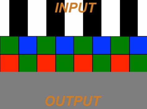
And lets assume we are using a bayer sensor such as the one in the FS700, F5 or F55 that has a pixel arrangement like this, although it’s worth noting that aliasing can occur with any type of sensor pattern or even a 3 chip design:
Sensor with bayer pattern.
Now lets see what happens if we shoot our test pattern so that the stripes of the pattern line up with the pixels on the sensor. The top of the graphic below represents the pattern or image being filmed, the middle is the sensor pixels and the bottom is the output from the green pixels of the sensor:
Test pattern aligned with the sensor pixels.
As we can see each green pixel “see’s” either a white line or a black line and so the output is a series of black and white lines. Everything looks just fine… or is it? What happens if we move the test pattern or move the camera just a little bit. What if the camera is just a tiny bit wobbly on the tripod? What if this isn’t a test pattern but a striped or checked shirt and the person we are shooting is moving around? In the image below the pattern we are filming has been shifted to the left by a small amount.
Test pattern miss-aligned with pixels.
Now look at the output, it’s nothing but grey, the black and white pattern has gone. Why? Simply because the green pixels are now seeing half of a white bar and half of a black bar. Half white plus half black equals grey, so every pixel see’s grey. If we were to slowly pan the camera across this pattern then the output would alternate between black and white lines when the bars and pixels line up and grey when they don’t. This is aliasing at work. Imagine the shot is of a person with a checked shirt, as the person moves about the shirt will alternate between being patterned and being grey. As the shirt will be not be perfectly flat and even, different parts of the shirt will go in and out of sync with the pixels so some parts will be grey, some patterned, it will look blotchy. A similar thing will be happening with any colours, as the red and blue pixels will sometimes see the pattern at other times not, so the colours will flicker and produce strange patterns, this is the moiré that can look like a rainbow of colours.
So what can be done to stop this?
Well what’s done in the majority of professional level cameras is to add a special filter in front of the sensor called an optical low pass filter (OPLF). This filter works by significantly reducing the contrast of the image falling on the sensor at resolutions approaching the pixel resolution so that the scenario above cannot occur. Basically the image falling on the sensor is blurred a little so that the pixels can never see only black or only white. This way we won’t get flickering between black & white and then grey if there is any movement. The downside to this is that it does mean that some contrast and resolution will be lost, but this is better than having flickery jaggies and rainbow moiré. In effect the OLPF is a type of de-focusing filter (for the techies out there it is usually something called a birefringent filtre). The design of the OLPF is a trade off between how much aliasing is acceptable and how much resolution loss is acceptable. The OLPF cut-off isn’t instant, it’s a sharp but gradual cut-off that starts somewhere lower than the sensor resolution, so there is some undesirable but unavoidable contrast loss on fine details. The OLPF will be optimised for a specific pixel size and thus image resolution, but it’s a compromise. In a 4K camera the OLPF will start reducing the resolution/contrast before it gets to 4K.
(As an aside, this is one of the reasons why shooting with a 4K camera can result in better HD, because the OLPF in an HD camera cuts contrast as we approach HD, so the HD is never as sharp and contrasty as perhaps it could be. But shoot at 4K and down-convert and you can get sharper, higher contrast HD).
So that’s how we prevent aliasing, but what’s that got to do with 2K on the FS700, F5 and F55?
Well the problem is this, when shooting 2K raw or in the high speed raw modes Sony are reading out the sensor in a way that creates a larger “virtual” pixel. This almost certainly has to be done for the high speed modes to reduce the amount of data that needs to be transferred from the sensor and into the cameras processing and recording circuits when using high frame rates. I don’t know exactly how Sony are doing this but it might be something like my sketch below:
Using adjacent pixels to create larger virtual pixels.
So instead of reading individual pixels, Sony are probably reading groups of pixels together to create a 2K bayer image. This creates larger virtual pixels and in effect turns the sensor into a 2k sensor. It is probably done on the sensor during the read out process (possibly simply by addressing 4 pixels at the same time instead of just one) and this makes high speed continuous shooting possible without overheating or overload as there is far less data to read out.
But, now the standard OLPF which is designed around the small 4K isn’t really doing anything because in effect the new “virtual” pixels are now much larger than the original 4K pixels the OLPF was designed around. The standard OLPF cuts off at 4K so it isn’t having any effect at 2K, so a 2K resolution pattern can fall directly on our 2K virtual bayer pixels and you will get aliasing. (There’s a clue in the filter name: optical LOW PASS filter, so it will PASS any signals that are LOWer than the cut off. If the cut off is 4K, then 2K will be passed as this is lower than 4K, but as the sensor is now in effect a 2K sensor we now need a 2K cut off).
On the FS700 there isn’t (at the moment at least) a great deal you can do about this. But on the F5 and F55 cameras Sony have made the OLPF replaceable. By loosening one screw the 4K OLPF can be swapped out with a 2K OLPF in just a few seconds. The 2K OLPF will control aliasing at 2K and high speed and in addition it can be used if you want a softer look at 4K. The contrast/resolution reduction the filter introduces at 2K will give you a softer “creamier” look at 4K which might be nice for cosmetic, fashion, period drama or other similar shoots.
Replacing the OLPF on a Sony PMW-F5 or PMW-F55. Very simple.
Fs700 owners wanting to shoot 2K raw will have to look at adding a little bit of diffusion to their lenses. Perhaps a low contrast filter will help or a net or stocking over the front of the lens to add some diffusion will work to slightly soften the image and prevent aliasing. Maybe someone will bring out an OLPF that can be fitted between the lens and camera body, but for the time being to prevent aliasing on the FS700 you need to soften, defocus or blur the image a little to prevent the camera resolving detail above 2K. Maybe using a soft lens will work or just very slightly de-focussing the image.
But why don’t I get aliasing when I shoot HD?
Well all these cameras use the full 4K sensor when shooting HD. All the pixels are used and read out as individual pixels. This 4K signal is then de-bayered into a conventional 4K video signal (NOT bayer). This 4K (non raw) video will not have any significant aliasing as the OLPF is 4K and the derived video is 4K. Then this conventional video signal is electronically down-converted to HD. During the down conversion process an electronic low pass filter is then used to prevent aliasing and moiré in the newly created HD video. You can’t do this with raw sensor data as raw is BEFORE processing and derived directly from the sensor pixels, but you can do this with conventional video as the HD is derived from a fully processed 4K video signal.
I hope you understand this. It’s not an easy concept to understand and even harder to explain. I’d love your comments, especially anything that can add clarity to my explanation.
UPDATE: It has been pointed out that it should be possible to take the 4K bayer and from that use an image processor to produce a 2K anti-aliased raw signal.
The problem is that, yes in theory you can take a 4K signal from a bayer sensor into an image processor and from that create an anti-aliased 2K bayer signal. But the processing power needed to do this is incredible as we are looking at taking 16 bit linear sensor data and converting that to new 16 bit linear data. That means using DSP that has a massive bit depth with a big enough overhead to handle 16 bit in and 16 bit out. So as a minimum an extremely fast 24 bit DSP or possibly a 32 bit DSP working with 4K data in real time. This would have a big heat and power penalty and I suspect is completely impractical in a compact video camera like the F5/F55. This is rack-mount high power work station territory at the moment. Anyone that’s edited 4K raw will know how processor intensive it is trying to manipulate 16 bit 4K data.
When shooting HD your taking 4K 16 bit linear sensor data, but your only generating 10 bit HD log or gamma encoded data, so the processing overhead is tiny in comparison and a 16 bit DSP can quite happily handle this, in fact you could use a 14 bit DSP by discarding the two LSB’s as these would have little effect on the final 10 bit HD.
For the high speed modes I doubt there is any way to read out every pixel from sensor continously without something overheating. It’s probably not the sensor that would overheat but the DSP. The FS700 can actually do 120fps at 4K for 4 seconds, so clearly the sensor can be read in it’s entirety at 4K and 120fps, but my guess is that something gets too hot for extended shooting times.
So this means that somehow the data throughput has to be reduced. The easiest way to do this is to read adjacent pixel groups. This can be done during the readout by addressing multiple pixels together (binning). If done as I suggest in my article this adds a small degree of antialising. Sony have stated many times that they do not pixel or line skip and that ever pixel is used at 2K, but either way, whether you line skip or pixel bin the effective pixel pitch increases and so you must also change the OLPF to match.
When an engineer designs a gamma curve for a camera he/she will be looking to achieve certain things. With Sony’s Hypergammas and Cinegammas one of the key aims is to capture a greater dynamic range than is possible with normal gamma curves as well as providing a pleasing highlight roll off that looks less electronic and more natural or film like.
Recording a greater dynamic range into the same sized bucket.
To achieve these things though, sometimes compromises have to be made. The problem being that our recording “bucket” where we store our picture information is the same size whether we are using a standard gamma or advanced gamma curve. If you want to squeeze more range into that same sized bucket then you need to use some form of compression. Compression almost always requires that you throw away some of your picture information and Hypergamma’s and Cinegamma’a are no different. To get the extra dynamic range, the highlights are compressed.
Compression point with Hypergamma/Cinegamma.
To get a greater dynamic range than normally provided by standard gammas the compression has to be more aggressive and start earlier. The earlier (less bright) point at which the highlight compression starts means you really need to watch your exposure. It’s ironic, but although you have a greater dynamic range i.e. the range between the darkest shadows and the brightest highlights that the camera can record is greater, your exposure latitude is actually smaller, getting your exposure just right with hypergamma’s and cinegamma’s is very important, especially with faces and skin tones. If you overexpose a face when using these advanced gammas (and S-log and S-log2 are the same) then you start to place those all important skin tone in the compressed part of the gamma curve. It might not be obvious in your footage, it might look OK. But it won’t look as good as it should and it might be hard to grade. It’s often not until you compare a correctly exposed sot with a slightly over shot that you see how the skin tones are becoming flattened out by the gamma compression.
But what exactly is the correct exposure level? Well I have always exposed Hypergammas and Cinegammas about a half to 1 stop under where I would expose with a conventional gamma curve. So if faces are sitting around 70% with a standard gamma, then with HG/CG I expose that same face at 60%. This has worked well for me although sometimes the footage might need a slight brightness or contrast tweak in post the get the very best results. On the Sony F5 and F55 cameras Sony present some extra information about the gamma curves. Hypergamma 3 is described as HG3 3259G40 and Hypergamma 4 is HG4 4609G33. What do these numbers mean? lets look at HG3 3259G40
The first 3 numbers 325 is the dynamic range in percent compared to a standard gamma curve, so in this case we have 325% more dynamic range, roughly 2.5 stops more dynamic range. The 4th number which is either a 0 or a 9 is the maximum recording level, 0 being 100% and 9 being 109%. By the way, 109% is fine for digital broadcasting and equates to bit 255 in an 8 bit codec. 100% may be necessary for some analog broadcasters. Finally the last bit, G40 is where middle grey is supposed to sit. With a standard gamma, if you point the camera at a grey card and expose correctly middle grey will be around 45%. So as you can see these Hypergammas are designed to be exposed a little darker. Why? Simple, to keep skin tones away from the compressed part of the curve.
Here are the numbers for the 4 primary Sony Hypergammas:
The PMW-F5 and F55 are fantastic cameras. If you have the AXS-R5 raw recorder the dynamic range is amazing. In addition because there is no gamma applied to the raw material you can be very free with where you set middle grey. Really the key to getting good raw is simply not to over expose the highlights. Provided nothing is clipped, it should grade well. One issue though is that there is no way to show 14 stops of dynamic range in a pleasing way with current display or viewfinder technologies and at the moment the only exposure tool you have built in to the F5/F55 cameras are zebras.
My experience over many shoots with the camera is that if you set zebras to 100% and don’t use a LUT (so your monitoring using S-Log2) and expose so that your just starting to see zebra 2 (100%) on your highlights, you will in most cases have 2 stops or more of overexposure headroom in the raw material. Thats fine and quite useable, but shoot like this and the viewfinder images will look very flat and in most cases over exposed. The problem is that S-Log 2’s designed white point is only 59% and middle grey is 32%. If your exposing so your highlights are at 100%, then white is likely to be much higher than than the designed level, which also means middle grey and your entire mid range will be excessively high. This then pushes those mids into the more compressed part of the curve, squashing them all together and making the scene look extremely flat. This also has an impact on the ability to focus correctly as best focus is less obvious with a low contrast image. As a result of the over exposed look it’s often tempting to stop down a little, but this is then wasting a lot of available raw data.
So, what can you do? Well you can add a LUT. The F5 and F55 have 3 LUTS available. The LUTS are based either on REC709 (P1) or Hypergamma (P2 and P3). These will add more contrast to the VF image, but they show considerably less dynamic range than S-Log2. My experience with using these LUT’s is that on every shoot I have done so far, most of my raw material has typically had at least 3 stops of un-used headroom. Now I could simply overexpose a little to make better use of that headroom, but I hate looking into the viewfinder and seeing an overexposed image.
Why is it so important to use that extra range? It’s important because if you record at a higher level the signal to noise ratio is better and after grading you will have less noise in the finished production.
Firmware release 1.13 added a new feature to the F5 and F55, EI Gain. EI or Exposure Index gain allows you to change the ISO of the LUT output. It has NO effect on the raw recordings, it ONLY affects the Look Up Tables. So if you have the LUT’s turned on, you can now reduce the gain on the Viewfinder, HDSDI outputs as well as the SxS recordings (see this post for more on the EI gain). By using EI gain and an ISO lower than the cameras native ISO I can reduce the brightness of the view in the viewfinder. In addition the zebras measure the signal AFTER the application of the LUT or EI gain. So if you expose using a LUT and zebra 2 just showing on your highlights and then turn on the EI gain and set it to 800 on an F5 (native 2000ISO) or 640 on an F55 (native 1250ISO) and adjust your exposure so that zebra 2 is once agin just showing you will be opening your aperture by 1.5 (F5) or 1 (F55) stop. As a result the raw recordings will be 1.5/1 stop brighter.
In order to establish for my own benefit which was the best EI gain setting to use I spent a morning trying different settings. What I wanted to find was a reliable way to expose at a good high level to minimise noise but still have a little headroom in reserve. I wanted to use a LUT so that I have a nice high contrast image to help with focus. I chose to concentrate on the P3 LUT as this uses hypergamma with a grey point at 40% so the mid range should not look underexposed and contrast would be quite normal looking.
When using EI ISO 800 and exposing the clouds in the scene so that zebras were just showing on the very brightest parts of the clouds the image below is what the scene looked like when viewed both in the viewfinder and when opened up in Resolve. Also below is the same frame from the raw footage both before and after grading. You can click on any of the images to see a larger view.
P3 LUT, XDCAM recording, 800 EI ISO (PMW-F5).Raw footage, EI 800 ISO pre-grade.Raw, 800 ISO after grade. NO clipped highlights.
As you can see using LUT P3 and 800 EI ISO (PMW-F5) and zebra 2 just showing on the brightest parts of the clouds my raw footage is recorded at a level roughly 1.5 stops brighter than it would have been if I had not used EI gain. But even at this level there is no clipping anywhere in the scene, so I still have some extra head room. So what happens if I expose one more stop brighter?
The XDCAM recording, LUT P3, 800 EI, +1 stop, zebras showing over almost all clouds.Raw clip at +1 stop prior to grade.Raw at +1 stop after grade, no sign of any clipping.
So, as you can see above even with zebras over all of the brighter clouds and the exposure at +1 stop over where the zebras were just appearing on the brightest parts of the clouds there was no clipping. So I still have some headroom left, so I went 1 stop brighter again. The image in the viewfinder is now seriously over exposed.
The XDCAM recording at +2 stops, the sky and clouds look very overexposed.Raw clip, pre grading (LUT P3, EI 800). Looking scarily over exposed.After the grade the raw is looking much better, but there is a bit of clipping on the very brightest clouds.
The lower of the 3 images above is very telling. Now there is some clipping, you can see it on the waveform. It’s only on the very brightest clouds, but I have no reached the limit of my exposure headroom.
Based on these tests I feel very comfortable exposing my F5 in raw by using LUT P3 with EI gain at 800 and having zebra 2 starting to appear on my highlights. That would result in about 1.5 stops of headroom. If you are shooting a flat scene you could even go to 640 ISO which would give you one safe stop over the first appearance of zebra 2. On the F55 this would equate to using EI 640 with LUT P3 and having a little over 1.5 stops of headroom over the onset of zebras or EI 400 giving about 1 stop of headroom.
My recommendation having carried out these tests would be to make use of the lower EI gain settings to brighten your recorded image. This will result in cleaner, lower noise footage and also allow you to “see” a little deeper into the shadows in the grade. How low you go will depend on how much headroom you want, but even if you use 640 on the F5 or 400 on the F55 you should still have enough headroom above the onset of zebra 2 to stay out of clipping.
Manage your privacy
To provide the best experiences, we use technologies like cookies to store and/or access device information. Consenting to these technologies will allow us to process data such as browsing behavior or unique IDs on this site. Not consenting or withdrawing consent, may adversely affect certain features and functions.
Functional
Always active
The technical storage or access is strictly necessary for the legitimate purpose of enabling the use of a specific service explicitly requested by the subscriber or user, or for the sole purpose of carrying out the transmission of a communication over an electronic communications network.
Preferences
The technical storage or access is necessary for the legitimate purpose of storing preferences that are not requested by the subscriber or user.
Statistics
The technical storage or access that is used exclusively for statistical purposes.The technical storage or access that is used exclusively for anonymous statistical purposes. Without a subpoena, voluntary compliance on the part of your Internet Service Provider, or additional records from a third party, information stored or retrieved for this purpose alone cannot usually be used to identify you.
Marketing
The technical storage or access is required to create user profiles to send advertising, or to track the user on a website or across several websites for similar marketing purposes.