I’m really, really excited by HDR.
4K is cool, higher resolution, sharper pictures, but sometimes it’s tough to tell the difference between good HD and 4K, especially on a small screen. But HDR….. well HDR really does have that wow factor. Finally we will be able to see images on the screen that have contrast and brightness that is true to life. Vibrant, vivid high resolution images, no more muddy low contrast, dull images.
First of all, lets get this straight, this is not the same thing as the HDR photography that’s been around for an age where you take multiple images at different exposures to capture a massive dynamic range that you then process with photoshop or similar to create some kind of artistic but otherwise un-natural looking picture with un real contrast. Video HDR (or at least what’s being talk about now) is about displaying images on screens that have a dynamic range that closely matches the real world.
And you know what the best bit of this is? A lot of us already have cameras that are shooting HDR or that can be made at least partially HDR capable at no additional cost!
So what is HDR?
Historically television and cinema standards have been limited by display technology. Today a high quality LCD TV will only show a dynamic range of around 6 stops. If you have a light meter check it out. Measure the brightest whites and the deepest blacks and you should find a 5 to 6 stop range. Because cinema screens depend on reflecting light there are limits as to the contrast range that you will see in the cinema too. This has been the case since the very beginning of film making. Yet today we have cameras that can capture dynamic ranges well in excess of this, even an older camera such as a Sony EX1 can manage to record 11 stops, but with normal TV’s and monitors we have no way of showing this 11 stop (or more) range 1:1. So we massage the captured image to fit within the current conventional 6 stop display range using fancy things like the “knee” or special gamma curves like cinegamma, hypergamma or by grading and fine tuning the image in post production.
It’s all about the display.
The key technology that’s changing this is OLED displays. Remember dynamic range is not just about highlights but also about deep, dark shadows. We can make LCD screens brighter, much brighter. An LCD panel works by having a large light source behind an array of tiny electronically controlled ND filters. But these ND filters are never 100% dark, some light always leaks through. This means that when you make the back light brighter the blacks become less black as more light leaks through, so you don’t increase the contrast, only the brightness. The other issue is that current TV broadcasting standards (rec-709) are designed to work within the limitations of current display tech, so we don’t actually broadcast more than a 6 stop range. If we did the pictures wouldn’t look right on a 6 stop screen.
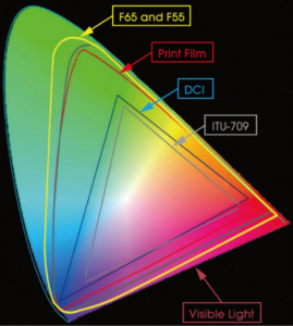
An OLED display on the other hand uses an array of individual LED emitters that are totally dark when they are off and can be very bright when all the way on. As a result they are capable of displaying a far greater dynamic range. TV and monitor manufacturers are now producing displays that are capable of showing dynamic ranges well in excess of the normal 6 stop range. If we then change the standard of the signals that we send to these displays to include a greater dynamic range that’s when the magic starts to happen. But it’s not just about contrast, it’s also about color. OLED displays can also show much more highly saturated colors.
You have to see it to believe it.

Unfortunately there is no way I can show you HDR here. Your computer monitor probably only has a 6 stop range. So to really see and appreciate HDR you are going to have to go and see a demo. There will be many at IBC. Imagine a picture of a sunset where the clouds and sky really are VIVID orange, an orange that positively glows from the screen illuminating the faces of the viewers. Meanwhile in the same shot there is a deep dark canyon in the foreground and you can see every detail in the deepest shadows of that canyon. Or how about a night time cityscape where the unlit buildings are dark but still clear to see, meanwhile the lights on the buildings are like tiny bright diamonds of brilliant light. Maybe the easiest to imagine is a shot across water where the ripples of the water catching the sun really, really do sparkle and catch your eye. But remember it’s not just about a brighter display, but ones with much, much greater contrast and much richer colors.
HDR Limits.
Are there limits to HDR? Well yes there are, but these limits are becoming more to do with what is comfortable to view rather than what the display technology can do. Sony’s X300 HDR monitor can show I believe around an 11 stop range. Some colorists have told me that working on HDR material in a dark grading suite for a few hours can be quite tiring due to the increased eyestrain. Let’s face it, we wouldn’t want a shot of the setting sun that is so bright that it makes your eye’s hurt. So in practice I think 10 to 11 stops is about the natural limit of what we will be comfortable watching on a screen at home. But this is an enormous 10 fold increase over what we have now.
It’s FREE! Well, at least shooting and distribution is.
One key thing about HDR is that it doesn’t need any more bandwidth to broadcast or distribute than any other image of the same size. All you need to do is change the gamma curve and color space used. This means that OTT (Over The Top – web and internet) delivery services such as Netflix or Amazon can stream in HDR without needing to make any changes to their infrastructure, all they need to do is grade the programme to suit an HDR display. Right now you can already find a number of movies to stream in HDR and many, many more programmes will be available from Netflix and Amazon Prime in HDR this year.
The next thing to consider is that if you have been shooting material with a camera dynamic range greater than 10 or 11 stops then you may already have content that is going to look great in HDR. S-Log material is perfect for HDR, material shot by the F55 using S-Gamut or S-Gamut3 is excellent for HDR as not only does it have a high dynamic range but it’s sensor also has a wide color gamut that will capture those highly saturated vibrant colors that only an HDR display can show. The F5 and FS7 will also shoot great material ready for HDR, although without some of the extended color range that the F55 is capable of. Even material shot with a Cinegamma or Hypergamma can be graded for HDR and in most cases will look better in HDR than it does on a conventional display.

So for us shooters, many of us already have equipment that can produce HDR content, in fact HDR will be the first time many of us will actually truly be able to see what we are shooting! To grade and produce HDR content you are going to need to invest in an HDR display. I’d love to get one of the new HDR capable Sony BVM-X300 monitors, but at £25k it’s too steep for me, so I will have to wait for a good quality HDR TV. The biggest issue with HDR will be that you will need to produce a different grade for HDR distribution compared to conventional Rec-709 distribution. But it must be remembered that many high end productions will already have different grades depending on the distribution method. After all a DVD or Bluray Rec-709 release of a film will need a different grade to the DCI-P3 cinema release.
Like 4K, HDR is already here. It’s not mainstream just yet, but it really isn’t far away. This isn’t a technology for the future, it’s a technology for today. Give it another 18 months and HDR TV’s will be common place in most TV stores, just as 4K TV’s are readily available now. Movie studios are sitting on huge archives of films that with a re-grade will look amazing in HDR. With the new 4K Bluray standard able to carry HDR content we really are looking at a tangible revolution in the quality of home viewing. Not just higher resolution but also higher contrast and dynamic range. If you are starting a big project now or want your material to have a long shelf life, you really should be shooting in 4K and using log or raw right now.
Better at home than in the cinema?
It’s interesting to consider that HDR is something that’s going to work much better in the home or at least via a display panel rather than via projection, so the home viewing experience may well exceed the cinema viewing experience (assuming that you have decent sized screen and good sound system). The next generation broadcasting standard Rec-2020 allows for HDR. These are exciting times times and in the coming weeks I’m hoping to spend some time over at Sony’s Digital Motion Picture Center at Pinewood to learn more about grading and producing content for HDR, the details of which I’ll share with you here.
Bureaucracy in the way in Europe 🙁
In Europe we may have a problem. For HDR to work TV’s need to be brighter. Brighter TV’s consume more energy. At the moment it’s hard to sell an HDR TV in Europe as most exceed the power consumption limits laid down by the EU for televisions which are based on typical LCD technology 🙁 So you may need to personally import an HDR TV from elsewhere.