Sony rate the ND filters in most of there cameras using a fractional value such as 1/4, 1/16, 1/64 etc.
These values represent the amount of light that can pass through the filter, so a 1/4 ND lets 1/4 of the light through. 1/4 is the equivalent to 2 stops ( 1 stop = half, 2 stops = 1/4, 3 stops = 1/8, 4 stops = 1/16, 5 stops = 1/32, 6 stops = 1/64, 7 stops = 1/128).
These fractional values are actually quite easy to work with in conjunction with the cameras ISO rating.
If you want to quickly figure out what ISO value to put into a light meter to discover the aperture/shutter needed when using the camera with the built in ND filters, simply take the cameras ISO rating and multiply it by the ND value. So 800 ISO with 1/4 ND becomes 800 x 1/4 = 200 (or you can do the maths as 800 ÷ 4). Put 200 in the light meter and it will tell what aperture to use for your chosen shutter speed.
If you want to figure out how much ND to use to get an equivalent overall ISO rating (camera ISO and ND combined) you take the ISO of the camera and divide by the ISO you want and this gives you a value “x” which is the fraction in 1/x. So if you want 3200 ISO then take the base of 12800 and divide by 3200 which gives 4, so you want 1/4 ND at 12800.
This is a common problem and something people often complain about. It may be that the LCD screen of their camera and the brightness of the image on their monitor don’t ever seem to quite match. Or after the shoot and once in the grading suite the pictures look brighter or darker than they did at the time of shooting.
A little bit of background info: Most of the small LCD screens used on video cameras are SDR Rec-709 devices. If you were to calibrate the screen correctly the brightness of white on the screen would be 100 Nits. It’s also important to note that this level is the level that is also used for monitors that are designed to be viewed in dimly lit rooms such as edit or grading suites as well as TV’s at home.
The issue with uncovered LCD screens and monitors is your perception of brightness changes according to the ambient viewing light levels. Indoors in a dark room the image on it will appear to be quite bright. Outside on a Sunny day it will appear to be much darker. It’s why all high end viewfinders have enclosed eyepieces, not just to help you focus on a small screen but also because that way you are always viewing the screen under the very same always dark viewing conditions. It’s why a video village on a film set will be in a dark tent. This allows you to then calibrate the viewfinder with white at the correct 100 NIT level and then when viewed in a dark environment your images will look correct.
If you are trying to use an unshaded LCD screen on a bright sunny day you may find you end up over exposing as you compensate for the brighter viewing conditions. Or if you also have an extra monitor that is either brighter or darker you may become confused as to which is the right one to base your exposure assessments on. Pick the wrong one and your exposure may be off. My recommendation is to get a loupe for the LCD, then your exposure assessment will be much more consistent as you will then always be viewing the screen under the same near ideal conditions.
It’s also been suggested that perhaps the camera and monitor manufacturers should make more small, properly calibrated monitors. But I think a lot of people would be very disappointed with a proper calibrated but uncovered display where white would be 100 NITs as it would be too dim for most outside shoots. Great indoors in a dim room such as an edit or grading suite but unusably dim outside on a sunny day. Most smaller camera monitors are uncalibrated and place white 3 or 4 times brighter at 300 NIT’s or so to make them more easily viewable outside. But because there is no standard for this there can be great variation between different monitors making it hard to understand which one to trust depending on the ambient light levels.
Sadly this is not an uncommon problem. Suddenly and seemingly for no apparent reason the SDI (or HDMI) output on your camera stops working. And this isn’t a new problem either, SDI and HDMI ports have been failing ever since they were first introduced. This issue affects all types of SDI and HDMI ports. But it is more likely with higher speed SDI ports such as 6G or 12G as they operate at higher frequencies and as a result the components used are more easily damaged as it is harder to protect them without degrading the high frequency performance.
Probably the most common cause of an SDI/HDMI port failure is the use of the now near ubiquitous D-Tap cable to power accessories connected to the camera. The D-Tap connector is sadly shockingly crudely designed. Not only is it possible to plug in many of the cheaper ones the wrong way around but with a standard D-Tap plug there is no mechanism to ensure that the negative or “ground” connection of the D-Tap cable makes or breaks before the live connection. There is a however a special but much more expensive D-Tap connector available that includes electronic protection against this very issue (although a great product, even these cannot totally provide protection from a poor ground connection) – see: https://lentequip.com/products/safetap
Imagine for a moment you are using a monitor that’s connected to your cameras SDI or HDMI port. You are powering the monitor via the D-Tap on the cameras battery as you always do and everything is working just fine. Then the battery has to be changed. To change the battery you have to unplug the D-Tap cable and as you pull the D-Tap out, the ground pin disconnects fractionally before the live pin. During that extremely brief moment there is still positive power going to the monitor but because the ground on the D-Tap is now disconnected the only ground route back to the battery becomes via the SDI/HDMI cable and back through the camera. For a fraction of a second the SDI/HDMI cable becomes the power cable and that power surge blows the SDI/HDMI driver chip or damages the cameras motherboard.
After you have completed the battery swap, you turn everything back on and at first all appears good, but now you can’t get the SDI or HDMI output to work. There’s no smoke, no burning smells, no obvious damage as it all happened in a tiny fraction of a second. The only symptom is a dead SDI or HDMI.
And it’s not only D-Tap cables that can cause problems. A lot of the cheap DC barrel connectors have a center positive terminal that can connect before the outer barrel makes a good connection. There are many connectors where the positive can make before the negative.
You can also have problems if the connection between the battery and the camera isn’t perfect. A D-Tap connected directly to the battery might represent an easier route for power to flow back to the battery if there is corrosion on the battery terminals or a loose batter plate or adapter.
It can also happen when powering the camera and monitor (or other SDI connected devices like a video transmitter or timecode box) via separate mains adapters. The power outputs of most of the small, modern, generally plastic bodied switch mode type power adapters and chargers are not connected to ground. They have a positive and negative terminal that “floats” above ground at some unknown voltage. Each power supplies negative rail may be at a completely different voltage compared to ground. So again an SDI or HDMI cable connected between two devices, powered by different power supplies will act as the ground between them and power may briefly flow down the SDI cable as the SDI cables ground brings both power supply negative rails to the same common voltage. Failures this way are much less common, but they do still occur.
For these reasons you should always connect all your power supplies, power cables, especially D-Tap or other DC power cables first. Avoid using adapters between the battery and the camera as each adapter plate is another possible cause of trouble.
Then while everything remains switched off the very last thing to connect should be the SDI or HDMI cables. Only when everything is connected should you turn anything on. But beware – there is a myth that turning cameras and monitors off before plugging or unplugging is enough to stop this issue. This simply isn’t true because power is fed to the monitor and camera even when they are switched off so power loops and surges can still occur.
If unplugging or re-plugging a monitor (or anything else for that matter) turn everything off first. Do not connect or disconnect anything while any of the equipment is on. Although the greatest moment of risk is the moment you connect or disconnect any power cables such as when swapping a battery where you are using a D-Tap to power any accessories.
So, if changing batteries, switch EVERYTHING off first, then disconnect your SDI or HDMI cables before disconnecting the D-Tap or other power cables. Seriously – you need to do this, disconnect the SDI or HDMI before changing the battery if the D-Tap cable has to be unplugged from the battery. Things are a quite a bit safer if any D-Tap cables are connected directly to the camera or a power plate that remains connected to the camera as this way you can change the battery without needing to unplug the D-Tap cables and this does reduce the risk of issues.
Also inspect your cables regularly, check for damage to the pins and the cable, if you suspect that a cable isn’t perfect – throw it away, don’t take the risk. I’ve seen plenty of examples of D-Tap cables where one of the wires has broken off the connector pins.
A great safety check is to turn on your monitor immediately after connecting the power, but before connecting any SDI or HDMI cables. If the monitor comes on OK, this is evidence that the power is correctly connected. Then you can connect the SDI or HDMI cable. However, while a really good idea, this only indicates that there is some power to the monitor, it does not ensure that the ground connection is 100% OK.
The reason Arri talk about shielded power cables is because most shielded power cables use connectors such as Lemo or Hirose where the body of the connector is grounded to the cable shield. This helps ensure that when plugging the power cable in it is the ground connection that is made first and the power connection after. Then when unplugging the power breaks first and ground after. When using properly constructed shielded power cables with Lemo or Hirose connectors it is much less likely that these issues will occur (but not impossible).
Is this an SDI/HDMI fault?
No, not really. The fault lies in the use of power cables that allow the power to make before the ground or the ground to break before the power. A badly designed power connector often made as cheaply as possible. D-Tap was originally designed to be used to be used with high power video lights, it wasn’t designed to be used with delicate monitors and the design will allow it to be plugged in the wrong way around if you force it.
Additionally it could be user error. I know I’m guilty of rushing to change a battery and pulling a D-Tap connector without first disconnecting the SDI on many occasions, but so far I’ve mostly gotten away with it (I have blown an SDI on one of my Convergent Design Odysseys).
If you are working with an assistant or as part of a larger crew do make sure that everyone on set knows not to plug or unplug power cables or SDI cables without checking that it’s OK to do so – and always unplug the SDI/HDMI before disconnecting or removing anything else.
How many of us have set up a camera, powered it up, got a picture in the viewfinder and then plugged in the monitor via an SDI or HDMI cable? Don’t do it! Plug and unplug in the right order – connect ALL power cables and power supplies first. Check power is going to the camera and check power is going to the monitor by turning them on, then finally plug in the SDI. When removing a battery, unplug the SDI/HDMI, power down the camera and only then remove the D-Tap from the battery.
I’ve covered this before, but as this came up again in an online discussion I thought I would write about it again. For decades when I was doing a lot of corporate video work we shot greenscreen and chroma key with analoge or 8 bit, limited dynamic range, standard definition cameras and generally got great results (it was very common to use a bluescreen as blue spill doesn’t look as bad on skin tones as green). So now when we have cameras with much greater dynamic ranges and 10 bit recording is it better to shoot for greenscreen using S-Log3 (or any other log curve for that matter) or perhaps Rec-709?
Before going further I will say that there is no yes-no, right-wrong, answer to this question. I will also add that Rec-709 gets a bad rap because people don’t really understand how gamma curves/transfer functions actually work and how modern grading software is able to re-map the aquisition transfer function to almost any other transfer function. If you use a colour managed workflow in DaVinci Resolve it is very easy to take a Rec-709 recording and map it to S-Log3 so that you can apply the same grades to the 709 as you would to material originated using S-Log3. Of course the 709 recording may not have as much dynamic range as an S-Log3 recording, but it will “look” more or less the same.
Comming back to shooting greenscreen and chromakey:
S-Log3: ? Shoot using 10 bit S-log3 and you have 791 code values available (95-886) to record 14/15 stops of dynamic range. so on average across the entire curve each stop has around 55 code values. Between Middle Grey and +2 stops there are approx 155 code values – this region is important as this is where the majority of skin tones and the key background are likely to fall.
Rec-709: ? Shoot using vanilla Rec-709 and you are using 929 code values (90-1019) to record 6/7 stops so each stop has on average across the entire curve has around 125 code values. Between Middle Grey and +2 stops there are going to be around 340 code values. ? That is not an insignificant difference, it’s not far off the difference between shooting with 10 bit or 12 bit. ? If you were to ask someone whether it is better to shoot using 10 bit or 12 bit I am quite sure the automatic answer would be 12 bit because the general concensus is – more bits is always better. ? A further consideration is that the Sony cameras operate at a lower ISO when shooting with standard gammas and as a result you will have an improved signal to noise ratio using 709 than when using S-log3 and this can also make it easier to achieve a good, clean, key. ? However you do also need to think about what it is you are shooting and how it will be used. If you are shooting greenscreen in a studio then you should have full control over your lighting and in most cases 6 or 7 stops is all you need, so Rec-709 should be able to capture everything comfortably well. If you are shooting outside with less control over the light perhaps Rec-709 won’t have sufficient range. ? If the background plates have been shot using S-Log3 then some people don’t like keying 709 into S-Log3. However a colour managed workflow can deal with this very easily. We should consider that 709 and S-Log3 in a workflow where grading is a big part should not be though of as “looks” but simply as transfer functions or maps of what brightness/saturation seen by the camera is recorded at what code value. Handle these transfer functions correctly via a colour managed workflow and both will “look” the same and both will grade the same within their respective capture limits. ? For an easy workflow you might chose to shoot the greenscreen elements using log with the same settings as the plates. There is nothing wrong with this, it works, it is a very commonly used workflow but it isn’t necessarily always going to be optimum. A lot of people will put a lot of emphasis on using raw or greater bit depths to maximise the quality of their keying, but overlook gamma choice altogether, simply because “Rec-709” is almost a dirty word these days. ? If you have more control, and want absolutely the best possible key, you might be better off using Rec-709. As you will have more data per stop which makes it easier for the keying software to identify edges and less noise. If using Rec-709 you want to chose a version of Rec-709 where you can turn off the camera’s knee as this will prevent the 709 curve from crushing the highlights which can make them difficult to grade. In a studio situation you shouldn’t need to use a heavy knee.
I suggest you experiment and test for yourself and not every situation will be the same, sometimes S-Log3 will be the right choice, other times Rec-709. ?
A question poped up today asking about how to expose S-Cinetone when shooting green screen. The answer is really quite simple – no differently to how you would expose S-Cinetone anywhere else. But, having said that it is important to understand that S-Cinetone is a bit different to normal Rec-709 and this needs to be considered when shooting for chroma key or green screen.
S-Cinetone’s highlight roll off and shoulder starts much lower than most “normal” rec-709 curves. From around 73% the gamma curve changes and starts to compress the levels and reduce contrast. In the shdows there is a variable toe that increases contrast at lower brightness levels. The nominal “normal” brightness levels are also lower, all part of the contemporary film like look S-Cinetone is designed to give. A 90% reflectivity reference white card would be exposed at approx 83% instead of the more normal 90% (if you were using a light meter you should end up with a 90% white card at 83IRE). A white piece of paper will be a bit brighter than this as printer and copier paper etc is designed to look as bright as possible, typically printer paper comes out around 3 to 5% brighter than a proper white card.
The lower start to the highlight roll-off means that if you place skintones around 70% the brighter parts of a face will be affected by the rolloff and this will make them flatter. Expose skin tones at 60% and the face will be more contrasty and in my opinion look better. Although darker this would still be well with the “normal” exposure range for S-Cinetone so you will not have excessive noise and it will still key well.
S-Cinetone would be considered correctly exposed when a 90% white card is exposed between 78% and 88%. This is quite a wide window and is due to the way S-Cinetone is designed to give differening contrast levels simply by exposing a touch brighter or darker. The variable toe and shoulder mean that exposing brighter will make the image flatter and exposing darker more contrasty. Exposing as you would with normal Rec-709 levels with a white card at 90% will place skintones rather higher than “normal” and they will appear very flat. So either expose so a white card falls in the 78-88% window or use a calibrated monitor to observe how the skin tone look and be careful not to overexpose them.
Your greenscreen should be between 40IRE and 60IRE for a good clean key, I normally aim for 50IRE with S-Cinetone, but provided you don’t go below 40IRE or above 60IRE you should be good.
This is a question that comes up a lot. Especially from those migrating to a camera with a CineEI mode from a camera without one. It perhaps isn’t obvious why you would want to use a shooting mode that has no way of adding gain to the recordings.
If using the CineEI mode shooting S-log3 at the base ISO, with no offsets or anything else then there is very little difference between what you record in Custom mode at the base ISO and CineEI at the base EI.
But we have to think about what the CineEI mode is all about. It’s all about image quality. You would normally chose to shoot S-Log3 when you want to get the highest possible quality image and CineEI is all about quality.
The CineEI mode allows you to view via your footage via a LUT so that you can get an appreciation of how the footage will look after grading. Also when monitoring and exposing via the LUT because the dynamic range of the LUT is narrower, your exposure will be more accurate and consistent because bad exposure looks more obviously bad. This makes grading easier. One of the keys to easy grading is consistent footage, footage where the exposure is shifting or the colours changing (don’t use ATW with Log!!) can be very hard to grade.
Then once you are comfortable exposing via a LUT you can start to think about using EI offsets to make the LUT brighter or darker. When the LUT is darker you open the aperture or reduce the ND to return the LUT to a normal looking image and vice versa with a brighter LUT. This then changes the brightness of the S-log3 recordings and you use this offsetting process to shift the highlight/shadow range as well as noise levels to suit the types of scenes you are shooting. Using a low EI (which makes the LUT darker) plus correct LUT exposure (the darker LUT will make you open the aperture to compensate) will result in a brighter recording which will improve the shadow details and textures that are recorded and thus can be seen in the shadow areas. At the same time however that brighter exposure will reduce the highlight range by a similar amount to the increase in the shadow range. And no matter what the offset, you always record at the cameras full dynamic range.
I think what people misunderstand about CineEI is that it’s there to allow you to get the best possible, highly controlled images from the camera. Getting the best out of any camera requires appropriate and sufficient light levels. CineEI is not designed or intended to be a replacement for adding gain or shooting at high recording ISOs where the images will be already compromised by noise and lowered dynamic range.
CineEI exists so that when you have enough light to really make the camera perform well you can make those decisions over noise v highlights v shadows to get the absolute best “negative” with consistent and accurate exposure to take into post production. It is also the only possible way you can shoot when using raw as raw recordings are straight from the sensor and never have extra gain added in camera.
Getting that noise/shadow/highlight balance exactly right, along with good exposure is far more important than the use of external recorders or fatter codecs. You will only ever really benefit fully from higher quality codecs if what you are recording is as good as it can be to start with. The limits as to what you can do in post production are tied to image noise no matter what codec or recording format you use. So get that bit right and everything else gets much easier and the end result much better. And that’s what CineEI gives you great control over.
When using CineEI or S-Log3 in general you need to stop thinking “video camera – slap in a load if gain if its dark” and think “film camera – if its too dark I need more light”. The whole point of using log is to get the best possible image quality, not shooting with insufficient light and a load of gain and noise. It requires a different approach and completely different way of thinking, much more in line with the way someone shooting on film would work.
What surprises me is the eagerness to adopt shutter angles and ISO ratings for electronic video cameras because they sound cool but less desire to adopt a film style approach to exposure based on getting the very best from the sensor. In reality a video sensor is the equivalent of a single sensitivity film stock. When a camera has dual ISO then it is like having a camera that takes two different film stocks. Adding gain or raising the ISO away from the base sensitivity in custom mode is a big compromise that can never be undone. It adds noise and decreases the dynamic range. Sometimes it is necessary, but don’t confuse that necessity with getting the very best that you can from the camera.
The way the coax cables used for SDI works is very different to the way an HDMI cable works. HDMI cables are indeed constructed quite differently between early HDMI 1.0 – 1.4 classes and the more recent 2.0+ classes. So with HDMI you will find that an old, early version HDMI cable won’t work with the latest standards.
SDI cables are nothing fancy.
SDI uses nothing more sophisticated than a single core coax cable that is no different in it’s basic design, construction and mode of operation to an ordinary TV aerial down lead. It is a very simple type of cable and really nothing fancy.
Frequency matters.
The SDI signal is very high frequency; in effect it is a radio signal. From a cabling point of view the ONLY difference between the original SDI standard and the latest standards is the frequency. The way the cable works is no different between the original SDI standard and the latest and a camera or monitor has no way of telling or knowing what type of cable you are using.
Frequency is important because the higher the frequency, the more lossy ANY coax cable will become (leaky kind of describes what’s going on). Low quality cable – more signal leaks out, high quality cable less leaks out so the signal will go further.
But even the very earliest SDI cables were normally made using good quality very low loss coax. These original SDI cables are perfectly capable of carrying the higher frequencies used by 12G SDI. BUT over very long lengths there will be more loss at 12G than at 1.5G.
It’s not the “G” that counts, it’s the quality.
So really when looking for SDI cables, the question isn’t – “is it 12G” the question should be “what are the cable losses” or more simply “is it a good quality cable”. There are plenty of original SDI cables that can be used at 50m at 12G without issue. At the same time I have also seen cables marketed as “12G” that are nowhere near as well screened, with much higher losses, that barely work at 10m.
Just as important as the cable losses is the construction. Have the connectors been fitted correctly? Are the connectors correctly sized for the cable that’s being used, has the crimping or soldering been done well? Most coax cable failures are due to poor connector assembly or the use of low-quality connectors.
Impedance Matter.
One other thing to watch for is the cable impedance. SDI cables should be made using 75 ohm impedance cable and connectors. Radio cables for radio communications normally use 50 ohm cables and connectors and the two are not really compatible. But often cheaper cables sold for SDI and video applications may be made using 50 ohm parts as often these are cheaper. These cables will fit and more often than not they appear to work. BUT the pins in the BNC plugs are a different size and this can result in intermittent connections and over time can even damage the connectors on cameras and monitors etc. So do make sure your cables really are 75 ohm.
In the real world:
For most shorter cables, up to 5m cable losses are rarely an issue unless the cable is of particularly low quality or badly made. For between 5m and 10m you should avoid the very thin coax cables as the losses become more significant. Above 10m use only low loss cables with good quality screening. A cable sold as a “12G” cable should indicate good quality low loss cable, but it is not a guarantee. And the vast majority of well-constructed normal SDI cables will work just as well unless you want extremely long runs in which case you need ultra-low loss cable.
The FX6’s CineEI mode is designed to make shooting using S-Log3 or raw easy and straightforward. It optimises the camera so that settings such as the recording ISO, noise reduction and sharpening are all optimised for recording the highest possible quality S-Log3 or raw material with the largest possible dynamic range.
It makes sure that the S-Log3 or raw recordings are optimised for grading. In addition you can use a LUT (Look Up Table) in the viewfinder or on the HDMI/SDI output to provide a close approximation of how your footage will look after it’s been graded and this LUT will also to assist you in getting the exposure exactly right.
HINT: What is a LUT? A LUT is a simple Look Up Table of input values that represent different levels in the recording format (in this case S-Log3) and then converts those input values to new output values that are appropriate for the monitor or display range you are using. This conversion can included stylised adjustments to give the output image a specific look. A LUT can be applied to S-Log3 material to convert it so that it looks correct on a normal viewfinder or monitor.
To use the Cine EI mode correctly you must monitor what you are shooting via a LUT. Once you have a LUT enabled and you are viewing the LUT, either in the viewfinder or on a monitor an exposure offset can be applied to the LUT to make it darker or brighter than normal. This LUT brightness offset is used to allow you to deliberately offset how bright the recordings are, this is the “EI” or Exposure Index part of CineEI. More on that later.
BUILT IN LUTS
The FX6 has 3 built in LUTs, s709, 709(800) and S-Log3. In addition to the built in LUTs you can load your own “user MLUTs” into the camera as what the FX6 calls “Base Looks”. This makes this a very flexible and capable system. Sony refer to LUTs in the FX6 as MLUT’s or Monitor Look Up Tables. MLUTs = LUT’s they are not different.
Loading Your Own LUTs.
If you want to load you own LUTs into the camera these must be 3D Cube LUT’s and should be placed in the
— Private : SONY : PRO : LUT —
folder of an SD card or CFExpress card that has been formatted in card slot 2 of the FX6 (the lower slot). The LUT should be 17x or preferably 33x cube LUT designed for use with S-Log3 and SGamut3.cine. They are loaded via the main menu PAINT – BASE LOOK page.
The FX6 has 3 included LUT’s, these are s709, 709(800) and S-Log3. The AC-BCST LUT seen here is a user LUT that has been saved to the camera.
CODEC CHOICE.
As your material will require grading in post production, if you are shooting UHD or 4K you should NOT use XAVC-L because in UHD/4K XAVC-L is 8 bit 4:2:0. A much better choice is XAVC-I which is always 10 bit 4:2:2 and/or raw.
FIXED RECORDING ISO.
Once the camera is set to use the CineEI mode the recording sensitivity is fixed to either 800 ISO when in Lo Base sensitivity or 12,800 ISO when the camera is set to Hi Base sensitivity. These values cannot be changed and your recordings will always take place at one of these sensitivity levels.
Note: ISO and EI are not the same thing, even though they use similar numbers. ISO is very specifically the sensitivity of the camera, it is a measure of the sensors response to light. EI (Exposure Index) is a camera setting that alters the cameras EXPOSURE settings, EI does not change the sensitivity of the camera in any way.
ENABLE A MLUT (LUT).
To take full advantage of the Cine EI mode the next step is to enable a MLUT for the viewfinder and also optionally for the HDMI and SDI outputs. YOU MUST ENABLE A MLUT FOR CINE EI TO WORK.
My recommendation is as a minimum to enable a MLUT for the viewfinder. If you wish to record S-Log3 to an external recorder then you should not add a MLUT to the SDI/HDMI output. But if you are using an external monitor purely for monitoring it may be desirable to enable an MLUT for the SDI/HDMI output.
MLUT’s are enabled and disabled via status page 5 or in the main menu under Shooting – LUT NO/OFF
The default MLUT is Sony’s s709 LUT. This is the same LUT as used by the Venice digital cinema camera. s709 is designed to be a starting point for a film style look. To achieve this film style look it uses brightness levels more commonly found in feature films rather than the levels normally used in the majority of regular TV shows.
The default LUT is s709. The LUT can be changed from Status Page 5 or in the main menu under PAINT – BASE LOOK – SELECT
LUT EXPOSURE LEVELS
There are some important things to understand about different MLUTs and Base Looks. Each MLUT/Look will have it’s own optimum brightness levels. They will not all be the same. Some will be brighter or darker than others when exposed correctly, so it’s vital that you understand what levels any MLUT that you chose to use needs to be exposed at.
Another MLUT that the FX6 includes is Sony’s 709(800) LUT. This MLUT is more closely aligned with the levels used in normal TV productions, so it looks quite different to s709 and has very different brightness levels when exposed correctly.
The chart below gives the “correct” exposure values for S-Log3 as well as some guide values based on my own measurements for the s709 and 709(800) MLUTs found in the FX6.
Middle Grey
Average Skin Tones
90% Reflectivity white card (add 2-3% for white paper).
S-Log3
41%
48-52%
61%
s709
44-45%
57-62%
77-78%
709(800)
45-46%
65-70%
89%
MEASURING THE EXPOSURE.
There are many ways to measure your exposure when shooting using S-Log3 and MLUT’s. You could choose to use a light meter, in which case the light meter would be set to match the EI (Exposure Index) value set in the camera.
You can just look at the image in the viewfinder and judge when it looks right. Most of the time this is going to be OK, but it isn’t particularly accurate and if shooting outside in bright sunshine it may be difficult to see an unshaded LCD screen correctly.
My preferred method is to use a white card or grey card and then use the cameras built in video signal monitor and the waveform display to actually measure the brightness of the grey card or white card.
Note: When referring to a “white” exposure this means the exposure level of a white card that reflects 90% of the light that falls on it. It is not how bright your highlights are, or how bright clouds are. It is the brightness of a diffuse white card. A piece of white paper or a white shirt can be used if you don’t have a proper white card, but be aware that white printer paper or white fabrics are treated with brightening agents to make them look “bright” so white paper and white fabrics will be a little brighter, perhaps 94% reflectivity compared to 90% of a proper white card and this should be allowed for.
The Waveform Display.
The waveform display is enabled in the menu under MONITORING – DISPLAY ON/OFF – VIDEO SIGNAL MONITOR
If you are not familiar with a waveform display it is actually really easy to understand. The bottom of the waveform is black and the very top is 109%, the brightest that the camera can ever record to.
The left hand side is the left of the video image and the right is the right side of the video image. The thin grey reference lines across the waveform display are at 0% (the darkest a video image should ever normally be), 25%, 50%, 75% and 100%.
The levels shown by the FX6’s waveform display
In addition the FX6’s waveform display includes 2 yellow lines. The position of these yellow lines is determined by the levels that the cameras zebras are set to. By default the lower yellow line will be at 70% to match Zebra 1 and the upper line at 100% to match zebra 2.
WHAT ARE YOU MEASURING?
The waveform display measures the signal that is on the HDMI and the SDI output. So when you turn on the MLUT for the HDMI/SDI it is the levels of the MLUT that are being measured. If you don’t have an MLUT enabled for the SDI/HDMI then you will be measuring the recorded S-Log3 level. What the waveform is measuring is indicated just above the waveform display, in the example above we can see it is indicating LUT s709, so we are measuring the s709 LUT.
UNDERSTANDING HOW IT ALL WORKS.
To make it easier to understand how CineEI works I find it easier to start by turning OFF the LUT for the SDI and HDMI and measuring the exposure of the S-Log3. If you do this when the the Exposure Index (EI) is set so that it is equal to the Recording or Base ISO then you can use a white card or piece of white paper to establish the correct exposure for the S-Log3. Once you have done that you can then enable the MLUT and check the exposure of the LUT. So, lets see how we do that:
FIRST CHECK AND SET THE EXPOSURE INDEX LEVELS.
With the cameras base ISO set to low / 800 ISO I recommend that you set the EI levels in the main menu SHOOTING – ISO/Gain/EI as follows:
My recommended exposure index levels of 800/400/200 EI
ISO/GAIN BUTTON and CHANGING THE EI:
When using the CineEI mode you can change the EI value several ways. The most commonly used ways will likely be via the L/M/H ISO/Gain switch or by pressing the ISO/Gain button and then using the multi-function dial (MFD) to change the EI. Do note that when you use the multi-function dial or Direct Menu to change the EI this new EI setting changes the preset value associated with the current position of the L/M/H switch.
Personally I do not usually set an Exposure Index value that is higher than the base recording ISO value. The reason for this is that as you will see later, if you record using a high EI value your images will be noisy and grainy and could be very difficult to grade. Because you don’t ever see your final results until you get into post production, if you accidentally record noisy log you won’t really know how bad the footage will be until it is perhaps too late to do anything about it. So I set the EI for the Low Base 800 ISO as H>800EI, M>400EI, L>200EI. The difference between each of these EI’s is one stop and sticking to exact 1 stop increments makes it easier when you are checking any exposure changes.
For the 12,800 High base ISO I set the EI to H>12800EI, M>6400EI, L>3200EI.
FOR THIS EXAMPLE START AT LOW BASE/800 ISO and 800 EI.
By using the same EI as the base recording ISO there will be no offset or difference between the aperture, ND or shutter speed settings used for the correct exposure of the LUT and the correct, or “base exposure” for the S-Log3. Expose the LUT correctly and the S-Log3 will be also be normally exposed. Expose the S-Log3 normally and the LUT will look correct.
FOR THIS EXAMPLE LET’S START WITH THE SDI/HDMI LUT OFF.
For this example I am going to start with the LUT OFF for the SDI and HDMI, this way the waveform display will be measuring the S-Log3. Just above the waveform it should say SG3C/Slog3, telling you the waveform is measuring the S-Log3.
When the LUT (MLUT) is off for the SDI/HDM the waveform will be measuring the S-Log3 exposure level.
Referring to the table of exposure levels earlier in this article we can see that the correct exposure for S-Log3 using a white card (90% reflectivity white) is 61% – if using a normal piece of printer paper I suggest using a value a little higher (around 63%) as white paper tends to be a little brighter than a proper white test card. So, when measuring the S-Log3 we want to expose a white card at 61%. We can use the cameras zebras to help us find 61%.
SETTING ZEBRA 1 TO 61%
To make finding where 61% is on the waveform I recommend setting Zebra 1 to 61% so that the lower of the two yellow zebra lines on the waveform display is at 61%.
Set Zebra 1 to 61% via the main menu and MONITORING – ZEBRA.
So now when checking the exposure of a white card when the waveform is measuring the S-Log3, it is simply a case of adjusting the exposure until the white card is at the same level as the 61% line. Alternately you could use an 18% grey card, in which case you would set Zebra 1 to 41%, however there are often times when I forget my grey card but I almost always have a piece of paper somewhere.
White target exposed at 61% when measuring the S-Log3
So now we know that the S-Log3 is correctly exposed lets turn ON the LUT for the SDI and HDMI outputs and check the exposure level of the s709 LUT (or any other LUT that you wish to use – by setting the S-Log3 exposure first, you can then determine the correct exposure level of any LUT that you might wish to use).
NOW TURN ON THE SDI/HDMI LUT – DON’T CHANGE ANYTHING ELSE.
MLUT’s are enabled and disabled via status page 5 or in the main menu under Shooting – LUT NO/OFF
And if we refer to the exposure chart given towards the top of the page we will see that white for the s709 LUT is 77%. So now let’s set Zebra 2 to 77% to make 77% easier to find on the waveform. Do remember however that other LUTs may need different levels, 77% is just for s709, 709(800) would require Zebra 2 to be set to 89%.
SET ZEBRA 2 TO 77% FOR s709
Set Zebra 2 to the correct white level for the LUT you are using via the main menu and MONITORING – ZEBRA.
Now with the LUT ON for the SDI/HDMI we should see the brightness of the white card line up with the upper yellow line that represents Zebra 2 and 77%.
As you can see from the above example when the Base ISO and Exposure Index are matched, in this case the base ISO is 800 and the EI is 800, when the LUT for the SDI/HDMI is OFF and the white card is at 61% on the waveform the S-Log3 is correctly exposed. Then when the s709 LUT is ON for the SDI/HDMI the white card will be at 77%. We are correctly exposed. By having Zebra 1 set at 61% (for S-Log3) and Zebra 2 set for the white level for for your chosen LUT we can check either simply by turning the HDMI/SDI LUT ON or OFF.
USING THE 709(800) LUT INSTEAD
If you want a more contrasty looking image in the viewfinder and similar brightness levels to other video cameras – for example skin tones around 70% you might prefer to use the 709(800) LUT. When using the 709(800) LUT to measure a white card you should set Zebra 2 to 89%. It’s also worth noting that with the 709(800) LUT, if you wish, you could just leave the zebras at their default settings with Zebra 1 at 70% where just like a conventional Rec-709 video camera they will appear over brighter skin tones when viewing via the LUT.
CHANGING THE EXPOSURE INDEX TO OFFSET THE LOG EXPOSURE.
Sometimes it can be desirable to expose the S-Log3 a little brighter. For example when shooting scenes with a low average brightness level or scenes with large areas of shadows. The FX6 has very low noise levels at 800 ISO base. So, for most scenes with high average brightness levels there is not normally any need to expose the log any brighter than the normal Sony recommended levels. There is however a bit more noise at 12,800 ISO base. As a result it can be beneficial to expose the S-Log3 a bit brighter than the base level when using 12,800 ISO base to help keep the noise in the final image low.
CineEI Allows Accurate Control Over Exposure.
The CineEI mode makes this very easy to do in a very controlled manner. Keeping the amount of over exposure constant helps speed up the grading process as all your material can be graded in exactly the same way.
Over exposing or underexposing Log does not change the captured dynamic range, it will always be the same. However exposing log brighter will reduce the highlight range while at the same time increasing the shadow range. A brighter exposure will result in less noise after grading.
Exposing log darker will increase the highlight range but decrease the shadow range. A darker exposure will result in more noise after grading. Because under exposed log can become very noisy, very quickly I do not recommend under exposing log, because of this I strongly advise against ever using an EI that is higher than the base ISO as this will result in under exposed log.
CHANGING THE EI ONLY CHANGES THE LUT.
When you change the Exposure Index the only thing that actually changes is the brightness of the LUT. So for EI to work you must be monitoring via a LUT.
Below is what happens to the image in the viewfinder when you have a LUT enabled (s709 in this case) and you lower the EI from 800 EI down to 200 EI in 1 stop steps and make no changes to the exposure.
s709 at 800 EI and correctly exposed – note aperture is f8.s709 with the EI set one stop lower at 400 EI but no change to the exposure made, aperture is still f8.s709 now 2 stops darker at 200EI – no change to exposure, aperture is still f8
Changing the EI does not change the exposure in any way, the only thing changing is the brightness of the LUT. The recording levels have not yet changed in any way.
BUT NOW WE CHANGE THE EXPOSURE
At a lower than than base EI the image in the viewfinder is dark and the white card no longer reaches the correct exposure for the LUT, because we see this dark image and the level of the white card too low we now adjust the exposure to compensate.
In this example I simply opened the aperture by 2 stops from f8 to f4 to match the 2 stop change in the LUT brightness. Now the image in the viewfinder looks correct again and the white card is meeting the upper yellow line again (77% as set by Zebra 2 level).
The EI is at 200 but now the aperture has been opened by 2 stops to f4 so now the LUT is exposed correctly again.
BECAUSE THE EXPOSURE IS BRIGHTER THE S-LOG3 IS NOW ALSO BRIGHTER.
Because I have opened the aperture by 2 stops to make the 200 EI LUT exposure look right the S-Log3 recordings will now be 2 stops brighter. If I turn off the LUT for the SDI/HDMI we can see that the S-Log3 that will be recorded is now 2 stops brighter, the S-log3 white card level becomes 79%, so it appears slightly above the 77% Zebra 1 line.
After increasing the exposure by 2 stops to compensate for the 2 stop darker LUT (200EI) the S-Log3 recordings become 2 stops brighter and the S-Log3 white card level becomes approx 79%
By making the LUT darker by 2 stops, then adjusting the exposure upwards 2 stops to return the LUT to the original brightness we have made our recordings 2 stops brighter. This is how you use CineEI to alter the brightness of your recordings. A lower EI leads to a darker LUT and because the LUT looks dark we increase the exposure making the recording brighter. A brighter recording will have less noise than a darker recording.
At Low base ISO (800 ISO) the FX6 is a low noise camera, so there is no need to routinely over expose the log as there is with more noisy cameras like the FS5 or FS7. So I normally shoot at 800 EI. When using the high base ISO or 12,800 ISO there is a bit more noise and when using high base I will typically set the EI to 6400 EI as the 1 stop brighter recordings that this will result in helps compensate for the increased recording noise.
DYNAMIC RANGE and HIGHLIGHT/SHADOW RANGE:
When you shoot with a low EI the LUT will be dark and as a result f the dark viewfinder image you will expose brighter putting more light onto the cameras sensor. This brighter exposure will decrease the amount of noise in the final image and give you a greater shadow range. But at the same time it will decrease the highlight range that can be captured.
The S-Log3 levels that you will get when the EI value matches the cameras base ISO value, 800 ISO + 800 EI or 12,800 ISO + 12,800 EI. This is the base exposure and it gives 6 stops above middle grey and 8 stops below middle grey.
The S-Log3 levels that you will get when the EI value is 2 stops lower than the cameras base ISO value, in this case 800 ISO and 200 EI. Note how you now have 4 stops above middle grey and 10+ stops below. The final image will have less noise.
If you use a high EI value then the opposite happens. The brighter viewfinder image and higher LUT levels will make you want to expose darker to compensate. The resulting darker S-Log3 recording will have an increased highlight range but it will be considerably more noisy than recordings done at the base EI and will have a reduced shadow range. Generally I try to avoid ever using an EI value higher than the base ISO value. In a low light situation using a high EI value will make the image in the viewfinder brighter but on a small screen you won’t see the noise. I do not recommend using high EI values.
The S-Log3 levels that you will get when the EI value is 2 stops higher than the cameras base ISO value, in this case 800 ISO and 3200 EI. Note how you now have 8 stops above middle grey and 6+ stops below, the shadow range is reduced and the final image will also have significantly more noise.
IF YOU DON’T HAVE A WHITE CARD?
In the examples given here I have used a white card to measure and set the exposure. This is accurate and highly repeatable. But there will be times where you may not have a white card. At these times CineEI can still be used either by setting the Zebras to the appropriate skin tone levels for the chosen LUT (see the table towards the beginning) or by carefully “eyeballing” the brightness of the LUT image on the viewfinder screen or a monitor screen – if it looks right, it probably is right. If you are eyeballing it I highly recommend a deep sunshade or other device to exclude as much light as possible from the viewfinder. With a properly shaded viewfinder or monitor it is perfectly possible to shoot just by eyeballing the LUT’d image on the screen. As an exposure that is a little too dark is often going to cause more problems than an exposure that is a little too bright, if “eyeballing” the image I suggest using an EI that is 1 stop lower than the base EI. So in the case of the FX6 I would use 400 EI for low base ISO and 6400 EI for high base ISO.
CLIP PLAYBACK QUIRKS (YOU MUST ENSURE YOU HAVE UPDATED YOUR CAMERAS FIRMWARE as there was a bug in the initial release firmware that caused the playback EI to be applied back to front).
One great FX6 feature is that when you play back clips in the CineEI mode the camera can apply a LUT to the clip. Simply enable the LUT you want to use as you would when shooting. The FX6 applies then the EI offset that you have assigned to the L/M/H gain/ISO switch.
HOWEVER YOU DO THIS BE AWARE THAT THE L/M/H Gain switch alters the brightness of the clips when played back via a LUT. The only time there is no playback offset is when the switch is set to 800EI. So make sure you understand what EI it is you are looking at when playing back clips in CineEI as if you use the wrong EI your clips may appear over or under exposed.
I hope you found this guide useful. Good luck with your FX6, it is a very capable camera.
Changing the way the camera looks and using LUTs in Custom Mode:
You can also use any user LUTs that you have loaded into the camera to alter the base look when you are shooting in custom mode. For more information on that please watch the video below.
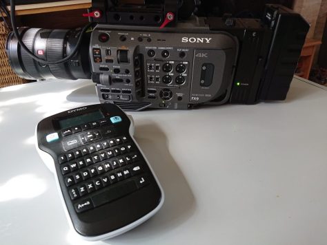
Maybe it’s just because I’m getting old, but I do like to have a label to remind me of what I have assigned to the assignable buttons on my cameras.
There are lot’s of ways you can make a label from a post-it-note to camera tape. But I recently got a new label printer from Dymo and with the right tape it will print white text on clear tape. The printers are around $40 so they are not too expensive. If you’re anything like me once you get one you will find yourself labelling everything, so a worthwhile investment.
Dymo labels for the assignable buttons on my PXW-FX9
For the labels on my FX9 I used the smallest “8” point text size and you will need to trim the labels down with a sharp pair of scissors. They need to be very small to fit in the gaps between the buttons. I found a pair of tweezers really helps to hold the label while you cut it and peel of the backing. Then you can use the tweezers to place your swanky new label exactly where you want it.
I think they look pretty good and are worth the effort. The printer I used is a Dymo Label Manager 160 and the tape is a Office Depot white on clear 12mm plastic tape. There are lots of colour choices if you don’t want clear tape. Looking at the pictures of the camera I now realise I should have taken a bit more time to get the labels straight! Fortunately you can peel them off without leaving any nasty residue or damaging the paint.
The dymo printer I used to knock up the labels.
Manage your privacy
To provide the best experiences, we use technologies like cookies to store and/or access device information. Consenting to these technologies will allow us to process data such as browsing behavior or unique IDs on this site. Not consenting or withdrawing consent, may adversely affect certain features and functions.
Functional
Always active
The technical storage or access is strictly necessary for the legitimate purpose of enabling the use of a specific service explicitly requested by the subscriber or user, or for the sole purpose of carrying out the transmission of a communication over an electronic communications network.
Preferences
The technical storage or access is necessary for the legitimate purpose of storing preferences that are not requested by the subscriber or user.
Statistics
The technical storage or access that is used exclusively for statistical purposes.The technical storage or access that is used exclusively for anonymous statistical purposes. Without a subpoena, voluntary compliance on the part of your Internet Service Provider, or additional records from a third party, information stored or retrieved for this purpose alone cannot usually be used to identify you.
Marketing
The technical storage or access is required to create user profiles to send advertising, or to track the user on a website or across several websites for similar marketing purposes.